Schaeffler Automotive Aftermarket (UK) provides a full replacement guide for the 2006 1.6 petrol model
Recommended fitting time: 3 hours LuK P/N: 622333200
Skoda introduced the Octavia in 1996, before releasing the the generation 3 in 2013. The Octavia has been a popular car since it was launched and is especially liked by taxi drivers due to its low CO2 cost, space and reliability. This model shares the same platform as other VAG group ‘A’ models with a transverse engine/transmission construction, so there is a good chance this will look quite familiar when the bonnet is raised.
In this guide we’re changing the clutch on a 2006 Skoda Octavia 1.6 petrol that had covered over 95,000 miles and the clutch had started slipping under full load. We used a two-post ramp and two transmission jacks for the repair.
On the ramp
With the vehicle positioned on the ramp, disconnect the air temperature sensor and breather pipe from the engine cover/air box assembly and remove the assembly. Now remove the battery covers, battery and battery tray to gain access to the top of the gearbox. Remove the two “C” clips that secure the gear linkage cables to the linkage (see Fig 1).
Remove the three mounting plate bolts before removing the gear cable assembly and stowing by the ABS unit.
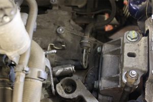
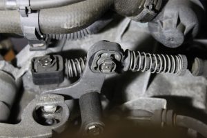
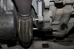
Now remove the clutch slave cylinder (the hydraulics don’t have to be disconnected) and unclip the flexible hydraulic pipe from the retaining bracket and swivel up (see Fig 2) – this will give better access to the two bolts. Remove the bolts, then the cylinder and then stow by the ABS unit (see Fig 3).
Now disconnect the wiring from the starter motor, pull back the rubber cover, release the red tab from the solenoid multiplug and then release the multi-plug. Now remove the main battery live cable from the
starter motor. The top starter motor bolt can also be removed at this point as well as the two top bell housing bolts.
With the car still on the floor, slacken the N/S/F hub bolt, raise the car and remove the engine under tray. Lower the car to waist height, remove the N/S/F wheel and then the lower section of the wheel arch liner. Now unbolt the N/S driveshaft flange (we used a long extension operating through the wheel arch area), disconnect the driveshaft from the gearbox and raise it above the gearbox casing.
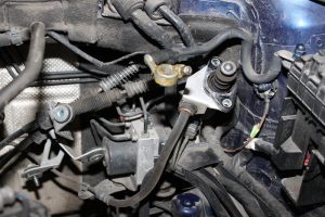
Then remove the hub bolt and slide it out from the hub before removing the driveshaft. Raise the car and unbolt the O/S inner driveshaft flange. Now disconnect the reverse light switch multi-plug and remove the bottom starter bolt and bracket. Remove the bottom gearbox mounting/stabiliser assembly and then the two bolts at the bottom of the bell housing (see Fig 4); these bolts can’t be fully removed (as the exhaust is in the way), but the final threads can be released as the gearbox is being removed.
Engine support
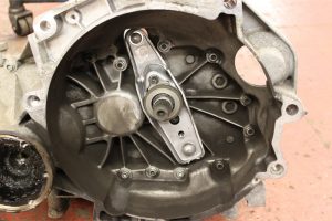
We now need to support the engine and gearbox assembly. The problem we have with this vehicle (and we’ll probably see more of it) is that there is no inner wing to locate an engine support beam on. The tool of choice would be an engine support that locates on the front subframe but this was not available to us so we instead supported the engine with a transmission jack and used a second transmission jack for the gearbox. Now remove the gearbox mounting and lower the engine and gearbox until clearance is available for gearbox removal. Remove the final two bell housing bolts and ease the gearbox out, remembering to release the two bottom bell housing bolts. With the gearbox removed, the clutch can now be removed.
The solid flywheel was inspected and the glaze removed from the surface with an emery cloth. Remove the clutch release fork, bearing and snout from the gearbox bell housing and clean the bell housing. Replace the gearbox snout, release fork and bearing, applying a smear of high melting point grease
to the pivot points of the release fork and the input shaft splines.
Clutch assembly
Check the clutch plate fits the input shaft splines correctly. This will also give even distribution of the lubrication and then allow you to wipe off any excess (see Fig 5).
Fit the new clutch assembly with a clutch alignment tool and torque to the manufacturer’s specification. Refit the gearbox, starting with the bottom two bell housing bolts during installation and, once bolted tight on the bell housing, refit the gearbox mounting and secure.
At this point we can check whether there is slight ‘freeplay’ on the release fork to confirm correct installation. Refit all components in reverse order and torque to the manufacturer’s specifications. You also need to ensure all electrical items are reset and working correctly as the battery has been disconnected. On start-up the ABS, ESP and electric steering warning lights were illuminated but, by turning the steering lockto-lock we were able to reset the steering. We could then reset the ABS and ESP by taking the vehicle for a short road test.


