
In the previous article on this subject, we illustrated how to recognise a healthy CAN Bus using a PC-based oscilloscope to observe the CAN frames, and using a simple ohmmeter to check the bus connections. Now we will explore how you can look at what is in the CAN frames with the use of a Windows-based analyser tool.
There are many fault code readers on the market that can tell you that there is a problem with the CAN Bus, but these tools are limited, in that they do not give you a true indication of where the fault really lies. This tool tells more than the typical fault code reader without the complication of complex analysis software.
Here we will show how you can tap into the CAN Bus and see all the CAN frames communicating between the ECUs. The picture below illustrates the basic structure of a CAN frame on the O-Scope.
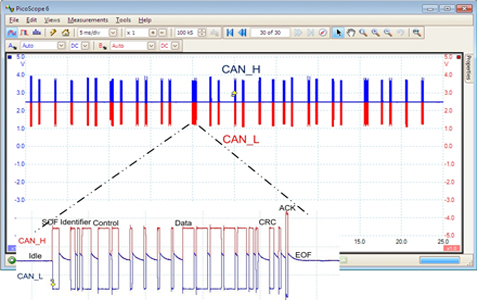
Here we illustrate a stream of CAN frames with a zoom in on one of the frames, showing the data parts of the frame
The CAN Frame
The CAN frame is comprised of a Start of Frame (SOF) bit, Identifier field (11 or 29 bits), Control Field (6 bits), Data field (up to 64 bits/8 bytes), Cyclic Redundancy Check (CRC) (16 bits), Acknowledge field (2 bits) and End of Frame (EOF) (7 bits).
The Identifier field indicates the nature of the data (e.g. engine parameters, ABS info, etc.). The Control field indicates the size of the Data field and contains what is known as the Data Length Code (DLC). The Data field is the information transferred (e.g. engine speed, water temp, oil temp, etc.). The CRC field is an error checking method to ensure the transferred data is not corrupted by any electro-magnetic disturbances. The Acknowledge field is a very simple method of indicating to the transmitting ECU that all the receiving ECUs have received the data uncorrupted. SOF and EOF are self explanatory.
The particular areas of interest for reading data from the CAN Bus are the Identifier and Data fields. There are several commercial Windows-based CAN analyser/test tools that are interfaced from the PC to the vehicle CAN Bus through a USB-to-CAN interface. These interfaces are readily available from several manufacturers and are connected to the vehicle CAN Bus via the OBD connector that is installed in all current cars.
CAN analysis tool
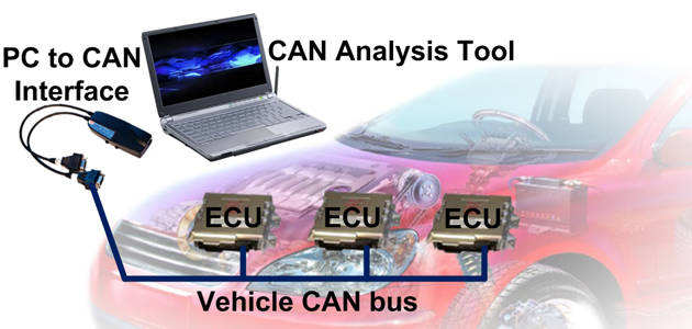
The CAN analysis tool (such as that shown above) shows a display of the Identifiers of the CAN frames and the data that is contained in those frames. The screenshot (below) shows how the CAN frames can be displayed.
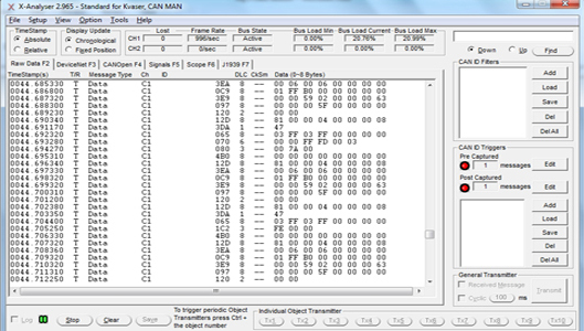
This shows how the CAN frames can be displayed
This is a good, quick indicator that CAN frames are being transferred between ECUs on the CAN Bus. Note that the display shows the Timestamps, Type of Frame (Data in most cases), Channel, ID (CAN frame Identifier), DLC (Date Length Code) and the Data. If you know the CAN database spec of your vehicle, it will be possible to ascertain which ID belongs to which ECU. The IDs and Data are shown in Hexadecimal, which is standard in the digital communications industry, however it is possible to display in Decimal if you wish. Also note that the bus frame rate and bus load of this CAN Bus system is shown as approx 20%. Max bus load of a powertrain type system is typically around 40%.
This tool can be useful for seeing disturbances on the CAN Bus by sensing Error Frames. The screenshot (see capture below) shows that at 44.77 seconds after start of collection, Error frames stated to occur. This is a real situation from a Jag S class that had an intermittent fault and was getting DTCs (Diagnostic Trouble Codes) indicating a problem with the ABS. With the CAN analyser attached, a technician moved the ABS ECU connector cable back and forth to check for bad connections. It was at this time Error frames were detected by the analysis tool.
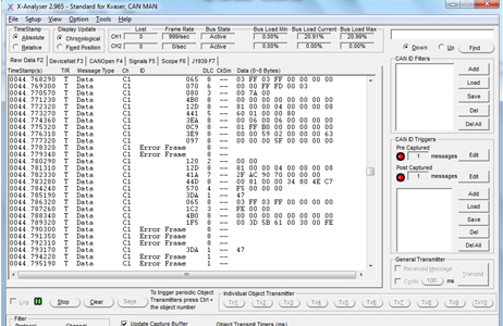
Here we can see that error frames were detected by the analysis tool
Database knowledge
On further inspection, it was determined that connections on the ABS ECU harness were faulty. With this software, it is possible to capture the data and play it back for analysis at a later stage.
As you can see in the Data field there are lot of values that will not immediately make sense to the casual observer. With CAN database knowledge for the vehicle, it is possible to interpret the data into real signals information (e.g. engine speed, wheel speed, etc.). The CAN database is a file that is generated based on the specification of your particular vehicle and most car companies have their own methods of interpreting CAN data. The CAN database will tell you what information is in each CAN ID. It also establishes how the raw digital data is extracted from the CAN frame and scaled before it is passed on to the microcontroller in the ECU for processing.
Warwick Control
Warwick Control provides both theoretical and practical training for CAN, CANopen, J1939, LIN, and FlexRay communication protocols. Training can be held at the Warwick Control offices or at the customer’s site.


