
 The job of the brake system is to decelerate the vehicle, as requested by the driver, and bring it safely to a stop at any time. This is achieved by the wheel brakes converting the kinetic energy of the vehicle into heat through friction; a process that can cause wear on both brake pads and discs.
Wheel brakes are also exposed to large temperature fluctuations such as water, road dirt and aggressive substances like road salt. For these reasons, the brake system should be thoroughly inspected at every service – or at least annually – and preferably just after winter. An inspection of the brake system is divided into three parts: the function test, the performance test and the visual inspection.
1) Function test
A function test can be carried out as the vehicle is being driven into the workshop. Here, the technician should check the brake pedal travel, operation of the brake lights and travel of the parking brake lever.
On most current braking systems, you shouldn’t be able to depress the brake pedal by more than 1/3of its full travel and it shouldn’t yield, even when depressed firmly. In order to exclude the influence of the brake booster, the pressure point of the brake pedal should be determined with the engine off and without any brake boosting. If the brake pedal feels soft and spongy, this may be an indication of air in the brake system or leaks in the brake hydraulics, for example. If the pedal travel is too long, always check the brake hoses too. When checking the brake pedal pressure point, you can also check the brake light switch and the pedal clearance at the same time. The brake light switch should activate the brake lights as soon as the brake pedal is touched gently.
When performing a function test on the parking brake, the general rule is to ensure that the brake lever travel is no more than five teeth. However, there are exceptions, so if in doubt follow the manufacturer specifications. You should also check that the parking brake lever locks in place securely in the engaged position and can be released easily afterwards. An excessively long brake lever travel is an indication of defective brake cables or worn rear axle brakes. If it is too short, the brake cables or other connecting elements may be rusted tight. It is also important to remember that incorrect basic adjustment can also affect the lever travel.
2) Performance test
The subsequent brake system performance test should be carried out on a brake test stand. In order to prevent any peripheral influences from affecting the results of the brake test, the vehicle must be conditioned prior to the performance test. Make sure that the tyre pressure is correct on all four wheels, that the tyre tread depth is the same on each axle and that the tyre sizes are approved and identical on each axle. Furthermore, the wheel suspension should not show any signs of damage and the axle geometry should be correct.
Measuring the rolling resistance
After the vehicle is driven onto the brake test stand, the brakes are first carefully applied to remove any dirt, moisture and signs of rust from the brake discs. To do so, maintain the brake pressure at a low level at first and then slowly increase it until you reach the ‘lock-up’ limit.
When the rollers start to run again, the wheels are first checked for unrestricted travel. The rolling resistance on a fully functional vehicle is typically between 100 and 300N. If the rolling resistance is too high, the brakes, wheel bearings and drive components must be checked for ease of movement.
Brake force comparison and fluctuation
The second step consists of slowly increasing the brake pressure to a brake force of 500 to 600N. At the same time you should check whether the brake force increases uniformly on the left and right wheel. An unbalanced increase in the brake force is a sign of tight brake callipers or wheel brake cylinders, oilfouled or greasy brake pads, rusted mechanical parts, glazed brake pads, air in the brake system or a clogged/pinched brake line or brake hose. On parking brakes, tight cables or incorrect basic adjustments are often the cause of an unbalanced increase in brake force.
The third step is to check the force fluctuation. Here, the brake force is held constant at a medium level. If the brake force indicator begins to fluctuate, this is a sign of a thickness tolerance or out-of-roundness, which can cause brake judder and steering wheel flutter when braking at high speeds. Thickness tolerances on disc brakes are caused by uneven wear on the brake disc, excessive lateral run-out on the brake disc or inadequate clearance. On drum brakes, brake force fluctuations are a result of warped or out-of-round brake drums. If the indicator fluctuates by more than 10% of the brake force, the brake system needs to be repaired.
Determining maximum brake force
After the force fluctuation check, the fourth and final step involves slowly increasing the pedal force until the wheels lock up and the test stand shuts off or the maximum brake force is reached. In this phase, it is also important to check that the brake force on the left and right wheels increases uniformly. The permissible brake force difference on an axle in the last 2/3 of the brake force curve is 25%, however it is advisable to determine the cause, even from a difference of 10%.
When braking at high speeds, even a small brake force difference can have a noticeable effect on the straightahead travel of the vehicle. In the case of parking brakes, the legal tolerance for maximum brake force difference is 50% as a general rule. These values may differ in the case of electric parking brakes however.
Finally the braking ratio is determined as a percentage, either by the brake test stand’s software, or manually. Here the total brake force is set against the permissible gross weight of the vehicle. For passenger cars, the law requires a minimum value of 50% for service brakes and 16% for the parking brake.
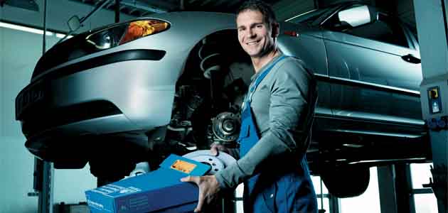
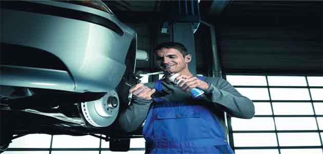
3) Visual inspection
Although the function test and performance test are very important, they provide no information about the wear status of the brake system. During the visual inspection, the technician first checks the brake fluid level in the expansion reservoir and then inspects the master brake cylinder for leaks. If the brake fluid level is too low, this is an initial indication of worn brakes or a leak in the hydraulic circuit.
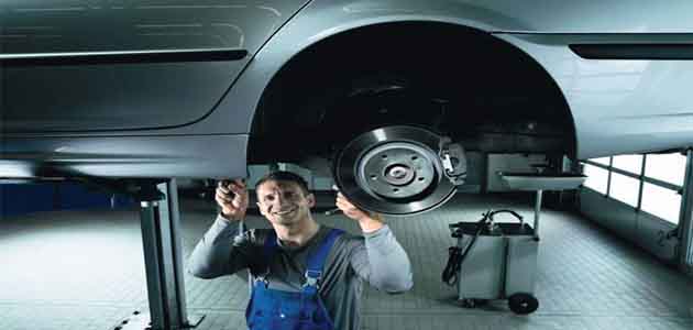
After this, raise the vehicle and inspect the other brake system components. The aim here is to determine whether:
a) The brake pads and discs are below the minimum thickness;
b) The brake hoses are porous or cracked;
c) The brake lines are damaged, correctly attached or pinched;
d) Brake fluid is escaping from the wheel brake cylinders or brake callipers;
e) The parking brake cables are intact;
f) (On combined callipers) the actuating lever of the parking brake contacts the limit stop when released.


