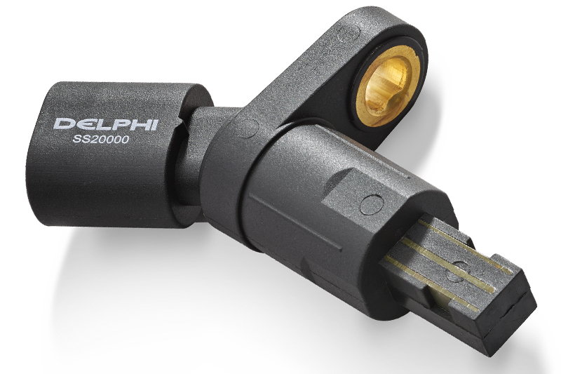
Delphi provides some guidance for getting to grips with ABS sensor diagnostics and replacement.
Braking components have continued to evolve over the past few decades, from drum and disc brakes to copper-free pads and disc coatings. Now, the addition of advanced electronic controls has enabled braking systems to become even safer and smarter than ever before.
As vehicles become better connected, technologies such as anti-lock brakes (ABS), electronic stability and brake assist are becoming commonplace. These advancements are just a selection of what technicians must keep up to date with, and companies such as Delphi Technologies are well positioned to provide the components and technical advice that workshop professionals need to service these increasingly complex vehicles.
Failing ABS sensors
Given its position within the ABS system near the road surface and associated debris, the reluctor wheel or tone ring can easily become dirty or damaged – as can the sensor.
This can result in weak or complete signal failure from the sensor. Other common causes of failure include breaks in wiring, sensor winding due to excessive vibration, or increased wheel bearing clearance.
Delphi Technologies says a faulty ABS sensor can impact several important braking functions and could exhibit the following warning signs:
ABS warning light: normally the first sign that there’s a problem with the system – this could be caused by either a sensor or control module fault. Once the ABS light has illuminated, the ABS system is automatically disabled and will not override manual braking.
Traction control light: since the ABS sensor also feeds data to the traction control system, issues could illuminate this light, too.
Reduced stopping power under heavy braking: the vehicle may take longer to stop or experience a loss of traction and control when braking heavily.
Less stability under wet or icy conditions: drivers may experience reduced traction and tyre slippage when driving on wet or icy roads.
Troubleshooting an ABS sensor
To identify the source of any sensor faults, Delphi suggests connecting a diagnostic tool to record the fault codes and check the live data. This process usually disables the ABS system. It then suggests using a multimeter and oscilloscope to check the supply voltages and signals, taking a measurement to test the line between control unit and sensor.
Next, inspect the sensor’s connectors and wiring to ensure they are correctly positioned, looking for signs of damage or contamination. Now do the same for the sensor and impulse ring. If at any stage components are contaminated, clean the contact surface using a wire brush.
How to replace a faulty ABS sensor
Once an ABS sensor fault has been identified, Delphi advises following these simple best practice sensor replacement steps:
- Loosen the wheel nuts before jacking the car up (do not remove wheel nuts yet). Consult the owner’s manual for correct jacking points and ensure that the vehicle is raised and supported securely
- Remove the wheels and move aside to access the brake system. (You may also need to remove the brake pads and discs). Once accessible, remove the bolt that holds the sensor onto the hub and the clips that secure the sensor wiring to the vehicle’s chassis/body
- Unplug the sensor
- Clean the area around the sensor with an emery cloth
- Working in reverse order, now install the replacement ABS sensor. Start by plugging in the sensor and then routing the harness back so it is secured to the body/chassis, then insert it into the hub
- If you had to remove the pads and discs, reinstall them and torque to the correct specifications
- Refit the wheels, tighten and lower the vehicle to the ground
- Torque tighten the wheels to the manufacturer’s specification
- Reconnect the diagnostic tool and dismiss any fault code(s). Run the engine and check for any new faults. If no faults display, exit the diagnostic software and switch off the ignition
- Finally, check that the ABS warning light has gone out and carry out a road test


