Suspension specialist Arnott explains how adaptive damping systems operate, providing a better understanding of how this suspension technology works.
As the automotive industry continues to enhance drivability and make the ride more comfortable, suspension technology plays an ever more important role. Suspension systems have been equipped with classic coil spring and shock absorber set-ups for a long time. Conventional leaf and coil spring systems evolved into air suspension systems and regular hydraulic shock absorbers evolved to highly advanced adaptive damping systems (that can be matched with both coil and air suspension systems). These innovations optimised the ride and handling for different driving conditions.
A typical modern adaptive ride control system contains the following components: adaptive dampers, an electronic control unit, a sensor set, and a driver preference switch. The sensor set is typically a combination of accelerometers that are located on the body, and position sensors located near the suspension at all four corners of the vehicle. Most vehicles with an adaptive damping system feature a driver preference switch. This is a button on the dashboard that allows the driver to select a preferred driving mode such as comfort or sport.
In this article, the “adaptive damper” can be any electronically controlled adjustable damper (including magnetic ride) since the basic operating principles for the system are the same.
How it works
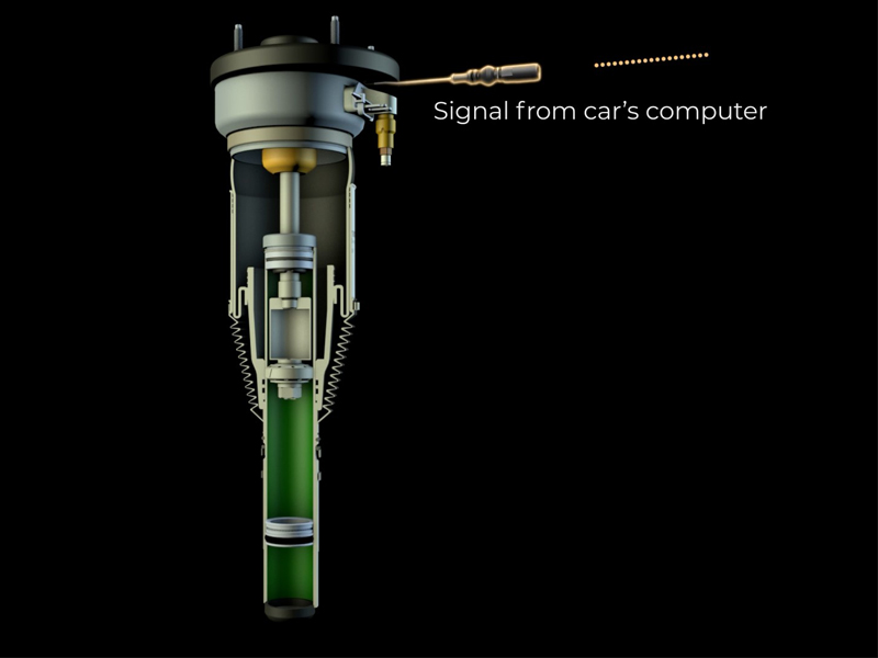
Adaptive damping systems began by using variable dampers with two or more discrete settings. The more modern adaptive systems use “continuously variable” dampers instead. The working principle between (older) discrete setting and (modern) continuously variable dampers is essentially the same. The difference is that in a discrete setting shock the valve is ON/OFF (fully open or fully closed), whereas a continuously variable valve allows the damper setting to be adjusted to any value between preestablished firm and soft setting limits. The ride control ECU is the brain of an adaptive damping system. The ECU is connected to sensors located on the body and the suspension at all four corners of the vehicle. Additionally, the ECU is also connected to the vehicle’s main data bus to get inputs including vehicle speed, throttle position, steering angle, transmission, and brake applications and others. The ECU receives these different data streams and uses them as inputs to an algorithm which continuously calculates the magnitude and direction of the vehicle’s body motions in heave, pitch, roll and yaw as well as the motion of each wheel relative to the vehicle body. The motion calculation results are then used to determine the damping force required at each individual corner of the vehicle to provide the desired ride and handling characteristics – as defined by the algorithm and the position of the driver preference switch. Once the ideal damping force has been calculated, the ECU provides the appropriate amount of electrical current to each damper to obtain the desired damping characteristics. This entire process occurs in milliseconds – more than fast enough to react to almost any road input. Except for the magnetic ride systems, the damping force of adaptive dampers are controlled in more or less the same way. The firm and soft damping force limits of adaptive dampers are controlled by shim stacks installed in separate flow passages within the damper. The damping force adjustment is typically achieved by opening or closing a fluid flow control valve to regulate the amount of fluid flowing through each flow passage.
For example, if a softer damping characteristic is needed in a continuously variable adaptive damper, the flow control valve will adjust so that more fluid will flow within the damper and will pass through the shim stack which defines the soft setting, and less fluid will flow through the passage containing the firm valve stack.
The next step
The Arnott eRide R&D team focuses on a collaboration with the continuously variable ride control systems currently being used by the different car manufacturers. Getting it right is quite a delicate process because electronic control strategy and the execution of that strategy is a combination of car manufacturer’s requirements and supplier offerings. The reality is that every ECU design works a little differently and the algorithms can be significantly different – even if the same shock design is being used.
To design and implement such technology for the aftermarket, it was crucial to make the eRide valve design functional and working in compliance with the variety of ECU set ups and valve designs. For example, the switching speed – which is the reaction time to switch between damper settings – can vary greatly. A change made for the switching speed for a particular application may work as improvement for a specific model but could actually cause performance issues for other vehicle applications. The eRide technology can be used to replace any continuously variable shock with an internal valve. Other valves with alternative designs are currently in development and will be released by the company at a later stage.
The continuous commitment and hard work of all the teams has led to a valve design that Arnott claims allows it to match or exceed OE ride and handling in all applications.


