
An air mass meter measures the mass of air entering the engine and converts this into an appropriate electronic signal for the ECU. This information is then utilised to determine the load the engine is under and to calculate fuelling and ignition timing.
How it works A small platinum wire or platinum film sensor sits inside the airflow to the engine. This sensor is maintained at a constant temperature, regardless of air flow. This is achieved by an electronic feedback loop that monitors the resistance of the heated sensor. As more air flows, the sensor is proportionally cooled and the feedback loop supplies more current to keep it at the required temperature. This current draw is then converted into a relative analogue voltage or pulse width modulated signal which is then fed into the ECU. An additional ambient temperature sensor allows for correction of the signal due to intake air temperature changes.
Reasons for failure
The film type sensors are very small. This allows for a very fast response to change in airflow, but the downside is that they become easily contaminated by small particles of dirt. As the dirt builds up on the platinum sensor it requires more current to heat it to the desired temperature which skews the reference signal to the ECU.
Although the AMM will still function it will be out of tolerance and can cause high fuel consumption, MOT emissions failure and poor performance. The self-diagnosis function of the ECU may not detect the problem until the sensor is vastly out of calibration. Other failures can be caused by connector or wiring issues.
Testing tips
A conventional fault code reader can be used to display the ECU’s stored fault codes. This is not a very reliable method as it can pick up AMM failures but will not highlight a calibration problem.
There are two main types of output from a modern AMM: analogue moving voltage, where the voltages increase with airflow; or pulse width modulation, where the gap between two pulses or the frequency changes with airflow.
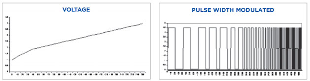
Testing with an oscilloscope or looking at a scan tool’s ‘live-data’ can be useful. The AMM can be tested actively but it can still be difficult to highlight slight out-of-tolerance failures. Testing this way will show any interference or connection problems.
Check the rise and fall of the output curve or PWM in direct response to revving the engine. You can also test the meter under load with the help of a rolling road or an on-road test.


