In the first of a two-part diagnostic marathon, Steve Smith, Automotive Application Specialist at Pico, describes how he went about correcting a camshaft correlation error in a Toyota Camry (import) with a quad-cam engine.
I am sure many of us have experienced the limitation of only having four PicoScope channels while being deep in a diagnosis battle. With the PicoScope software, we have the advantage of using reference waveforms to provide additional channels for comparison, so all is not lost. However, the acquisition of reference waveforms requires a robust technique to ensure that the timing correlates with the existing captures, and this has the potential to introduce a variable. Diagnosis commands that all variables are kept to a minimum, and from my perspective, there have been numerous occasions when six channels would have been perfect. The case study below is one such example.
Customer’s description
The customer reported that the engine warning lights (MIL) illuminated after two to three miles of driving with no loss of performance or drivability issues. The fault had been present since purchasing the vehicle approximately two months prior. The selling garage had replaced numerous components in an attempt to rectify the fault.Technical description
A road test of the vehicle proved no drivability issues and confirmed that the engine warning light was continually illuminated. Cycling the ignition and restarting the engine did not reset the MIL, which suggested that this was a permanent and present fault stored within the PCM.
Diagnosis
After verifying the customer’s complaint, we confirmed the vehicle’s ID and specification. The customer/garage interview highlighted a partial service history, a number of accessories installed, and the recent replacement of the following components:
- Engine oil and filter (including flush)
- Bank 1 intake camshaft position sensor
- Bank 1 camshaft timing gear bolts (with built-in oil control valve)
- Bank 1 VVT-i controllers (intake and exhaust)
- Bank 1 VVT-i solenoids (intake and exhaust)
- Timing chain tensioner assembly (between the intake and exhaust camshafts on Bank 1)
- Oil control valve filter removed, inspected and cleaned – minimal contamination found
- Engine ECU (PCM)
The basic inspection confirmed that the engine oil level and quality were good, that all visible components were correctly installed, and that the connections/harness routing in the engine bay were secure.
A vehicle scan of all onboard control units revealed the two fault codes listed below:
ENGINE-P0016 Crankshaft Position- Camshaft Position Correlation (Bank 1 Sensor A- Intake)
Main Body-B1245 Lost Communication with Wiper ECU LIN
Before we dive into what could cause these codes, it is paramount that we take a step back and check for technical bulletins (software updates, initialisation, recalls and campaigns, etc.). None were relevant for this vehicle. So, based on the two fault codes above, it makes sense to focus on P0016 given the nature of our fault.
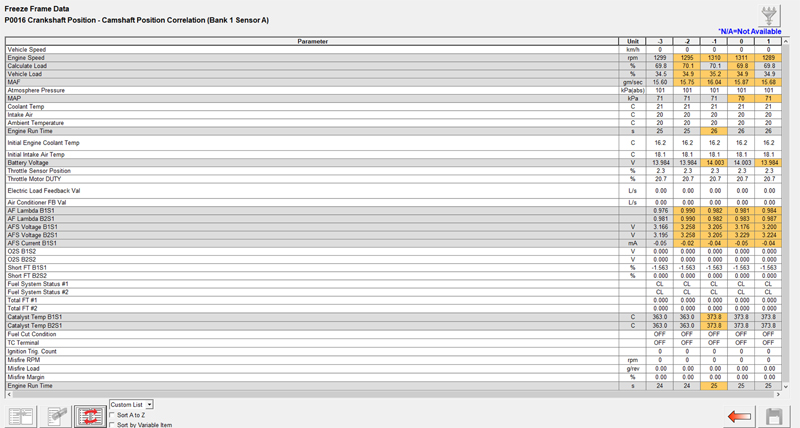
The fault code P0016 is accompanied by freeze frame data (engine parameters) pre and post-fault code detection, which enables simulation of the fault condition. As we can see here in Fig 1, the engine was running at fast idle (1,311rpm) during the ‘warming’ phase (coolant at 26°C).
Reproducing the fault
We erased all the fault codes and had the engine run at idle speed, where P0016 initially appeared as a pending code. This was followed by a current code after cycling the ignition and running the engine for a second time. From a diagnostic point of view, this is great news, as we know we are dealing with a permanent and present fault that the PCM has interpreted as a valid error.
My first question to the team was whether the components that were already replaced had timing marks. Were they correct and aligned? Replacing VVT-i controllers (camshaft timing gears) requires careful manipulation of the timing chain and tensioner. Without a doubt, the feedback from the technician involved was that the timing marks aligned correctly and, more importantly, that the associated bright links aligned with their respective markers to all timing gears.
The valve timing could therefore not be at fault as suggested by the fault code P0016 (camshaft position correlation (bank 1 sensor a)).
We referenced the description and operation data for in-depth knowledge of component location and functions. This knowledge is imperative when diagnosing any system and highlights the need for continual research and training. Toyota has a wonderful feature within their repair manual called ‘DTC Detection Condition’. This reveals the reason why P0016 has been stored along with possible causes under the heading of ‘Trouble Area’. The Detection Condition for P0016 informs of the following:
‘Deviation in the crankshaft position sensor signal and VVT sensor (for intake camshaft of bank 1) signal (2 trip detection logic).’
The Trouble Area informs:
- Valve timing
- Camshaft timing oil control valve assembly (for intake camshaft of bank 1, 2)
- Oil control valve filter (RH, LH)
- Oil pipe
- Camshaft timing gear assembly (bank 1, 2)
- ECM
What stands out immediately is that all of the above items have been replaced (except the oil pipe) and that valve timing is the first suggestion on the Trouble Area list.
Possible causes
- Oil pressure deviation to VVT-i Controller (camshaft timing gear)
- PCM misinterpretation of the camshaft position
- Dynamic valve timing error (beyond mechanical inspection)
The action plan
The action plan is predominantly governed by accessibility and probability.
- Confirm VVT-i operation
- Confirm dynamic valve timing against a known good vehicle
In keeping our initial diagnosis as non-intrusive as possible, we activated the camshaft VVT-I controllers for both Bank 1 and 2 via the scan tool to confirm the hydraulic operation. Here, the valve timing can be adjusted by each VVT controller, which has the desirable side effect of labouring the engine and introducing a stall due to inappropriate valve timing for idle speed conditions. All four of the VVT controllers were operating correctly and allowing the engine to stall. This confirmed that the oil supply and pressure were sufficient for VVT control.
To recap:
- Fault code P0016 was present and continual
- Numerous VVT components had been replaced
- The valve timing was confirmed to be correct (static inspection)
- The hydraulic operation of the VVT controllers was confirmed
- The PCM had been replaced
While non-intrusive techniques allow for evaluation and assessment of the vehicle, there comes a time where we have to intrude based on the evidence gathered. A dynamic valve timing check requires intrusion to the wiring harness/connectors and the disconnection of VVT-i controllers.
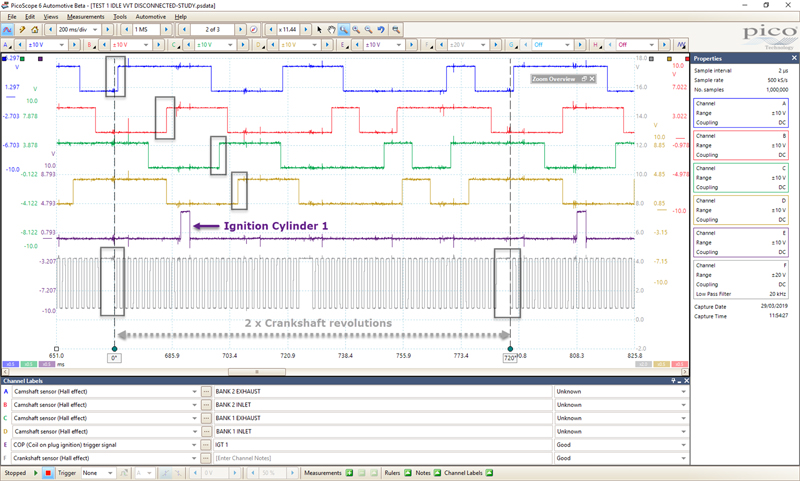
A minimum of five PicoScope channels are required for a quad-cam engine, given we now wish to measure the correlation between four camshafts as well as the crankshaft. The fact that we now have eight channels, with the PicoScope 4823 Automotive Diagnostic Oscilloscope, means that we don’t have to make any compromise or sacrifice to capture such measurements. As I still had channels to spare, I also included the cylinder 1 ignition event (IGT 1) as a synchronisation signal.
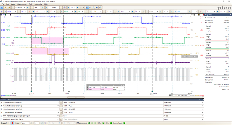
The following waveform shows the customer’s vehicle captured at idle speed with all VVT-i controllers disconnected. This allowed the camshafts to return to their default position (no VVT-I intervention). I have then highlighted our inspection points for camshaft and crankshaft correlation measurements. Here, I chose the first rising edge of each camshaft signal after the missing teeth of the crankshaft prior to the ignition event of cylinder 1 (Fig 2).
The rotation rulers identify two crankshaft revolutions (720°) and are located at the bottom right-hand corner of the scope screen. With 720° of crankshaft rotation identified on the screen, we can use the time rulers to measure the relationship between the crankshaft and the first rising edges of our chosen camshafts (in terms of crankshaft rotation). Below that (Fig 3), we have Bank 2 Exhaust Camshaft at 6.458° of crankshaft rotation after our 0° rotation ruler and the Bank 2 Inlet at 94.84°.
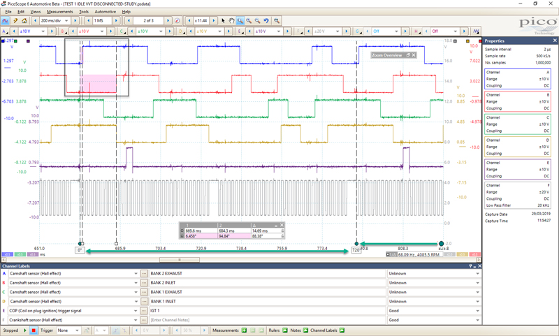
The process for Bank 1 camshafts is repeated below this (Fig 4), returning values of 190.3° for Bank 1 Exhaust and 224.1° for Bank 1 Inlet. The million-dollar question once again is: What does a good one look like? Normally at this point, we refer to the Waveform Library for a known good waveform, but at the time of diagnosis, a known good waveform was not available.