In the first of a two-part series, Jim Gilmour, Blue Print Technical Consultant, looks at the construction and operation of a Hyundai i30 EPS unit.
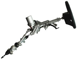 Electric Power Steering (EPS) or Motor Driven Power Steering (MDPS) has been around for the best part of two decades and is fitted to the majority of small and medium sized cars coming off today’s production lines. There are different types using different technologies but essentially the principles remain the same.
This is the first of two articles which looks at the column mounted type fitted to the Hyundai i30. The system was developed by TRW and is similar in operation to other systems.
Like any electromechanical component, the MDPS will eventually fail and the Hyundai unit is no exception.
So how do column-mounted MDPS systems work?
The mechanical components are fairly simple. The motor drives a worm shaft which turns a worm wheel giving the motor speed reduction and torque increase necessary to assist the driver in turning the steering column. The worm wheel is connected to the steering column shaft.
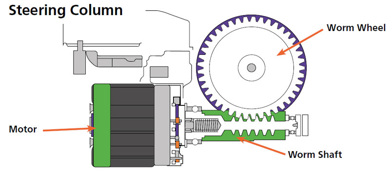
A computer receives information about how much steering torque the driver is applying and delivers a motor torque to suit. It all sounds very simple until you look at how the sensors and actuators have been designed with reliability in mind. Gone are brush and commutator DC motors and gone are carbon track steering angle sensors. These modern units use brushless motor technology (something we are going to see much more of in new and future vehicles) and contactless opto-electronics are used to provide information on the steering wheel torque and movement.
Direct Current Brushless motors (D.C.B.M)
The motor uses permanent magnets in the armature; modern rare earth magnets (neodymium) have very strong magnetic fields and this means that there is no need for armature windings and mechanical commutator which makes it more energy efficient and gets rid of the weakest part of any DC motor.
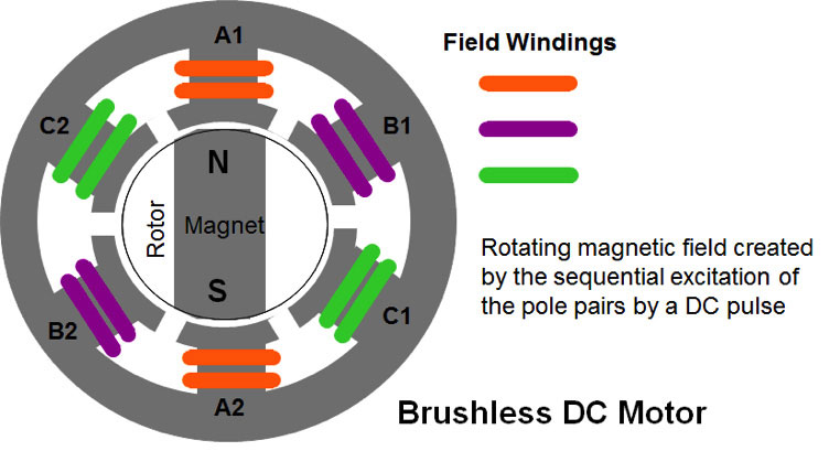
The EPS system uses a brushless motor, where the rotor (armature) turns inside the stator (there are other types). Three separate stator windings produce electromagnets. The polarity of the magnet depends on the direction of current flow so the current flowing through winding A from A1 to A2 will produce a south pole at A1 and north pole at A2. Reversing the flow from A2 to A1 will produce the opposite effect.
By switching the current flow to winding B, the rotor magnet is attracted to it (unlike poles attract) and the rotor turns in a clockwise direction. So by consecutively energising the three windings in order, the rotor will turn. Reversing the sequence will cause the rotor to turn anti clockwise.
The switching is done by transistors, or to be specific, the control system uses MOSFETs (Metal Oxide Semiconductor Field Effect Transistors) which have the ability to switch large currents at great speed and generate less heat than ordinary transistors.
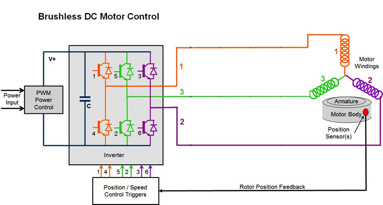
For example, switching on transistors 1 and 6 will energise stator coils 1 and 2. Switching on transistors 3 and 4 will also energise stator field coils 1 and 2 but the current will flow in the opposite direction and so the polarity of the stator magnets will be reversed. Sequencing the transistor switching will control the direction and by using Pulse Width Modulation (PWM) of the supply current, the speed and torque of the motor is controlled.
Speed and position
Switching of the field has to be synchronised to the position of the rotor and this is done by rotor position sensors. The Hyundai unit uses Hall sensors. Hall sensors are polarity sensitive and switch on and off as the poles of the sensor rotor move past it. There are three Hall sensors which mean that the controller can work out the position of the rotor even when it is stationary.
Steering torque and angle position sensor
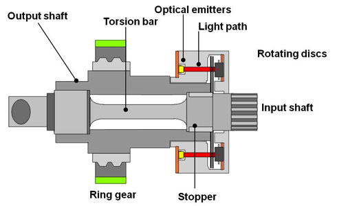
The MDPS unit fitted to the Hyundai uses a combined Steering torque and angle sensor and has no electrical contacts, which improves the reliability of the sensor.
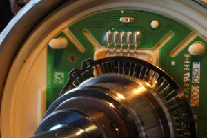
The upper and lower parts of the steering column are separated by a torsion bar which allows a small angle of displacement between the two shafts. The angle of displacement is relative to the torque applied and is limited by stops. Slotted discs with different width slots are connected to the upper and lower parts of the steering column. The slotted discs sit between a light source and a photodiode array that picks up the shadow created by the slotted discs. When the steering is turned the image is captured and both the displacement of the slots and the rate at which the steering discs are moving is processed to give steering torque, direction, steering angle position and rate of turn. There are two sensors in the system that sit opposite each other. The information from both sensors is compared for reliability and if one sensor should fail the system can still operate and a DTC will be set.
Proportionality
The motor assistance applied depends on the amount of torque applied to the steering wheel. When the steering wheel is turned, the torque applied is measured and a suitable torque is applied to the steering column by the motor. When the steering wheel is stopped, the motor continues to drive the lower part of the column until there is no load on the torsion bar and assistance stops.
Type recognition
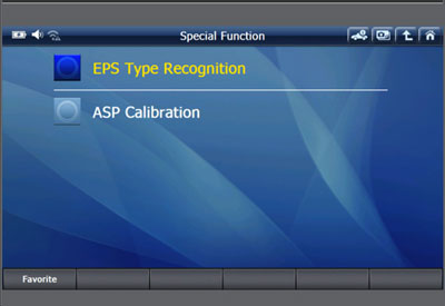 The characteristics of the steering unit differ from model to model. For instance, the heavier diesel engine version will require more assistance than the lighter petrol engine version. This is set at the factory (or at the remanufacturers and may need to be reset after installation.)
Absolute Steering Position (ASP)
This is the datum used to identify the straight ahead position. It is set in the factory (or remanufacturer) but may need to be reset after installation or if wheel alignment has taken place.
Both the ‘Type Recognition’ and ‘ASP’ can be lost if the battery is disconnected whilst the steering unit is active. You will need a suitable scantool such as the G-Scan or G-Scan2 to perform the task.
This article will be continued in the next edition of Blue Print magazine, and will look at the communication between the EPS unit and the rest of the vehicle, the safety features built into the system to protect the driver in the event of an electrical failure and the diagnostic data and trouble codes (DTCs) generated when a fault occurs.


