
Febi outlines the role sensors and electronics play in engine management.
Due to the evolution of the internal combustion engine, continuous enhancements to the efficiency and performance of vehicles have been paramount. This was achieved by improving the internal components and adding electronic engine management.
Today the electronic control of the engine requires a wide variety of different sensors to monitor the performance of fuel, air, ignition and emission-related events. This vital data is received by the vehicle’s control units which act on this information to control the many engine sub-systems using the various actuators that regulate the engine.
Modern engine management systems can assimilate megabytes of sensor information quickly, and control a multitude of engine actuators, whilst evaluating both sensor input and actuator data for plausibility and integrity.
This all forms the management system of the engine, which enhances the engine performance and provides smooth delivery of power and economy to meet the emissions standards and the driver’s expectations.
Sensors and actuators
Sensors, and the technology they use, control and regulate engine management systems. A sensor is a device able to acquire one or more physical parameters and convert them into another, which can be used more effectively to sense specific physical characteristics such as temperature, position, movement, speed etc. Sensors convert these characteristics into an electronically usable signal for the ECU to process.
Actuators are components which convert the electrical output signals from the ECU into physical quantities in order to control the internal combustion engine for efficiency, economy and performance. This includes parts such as fuel injectors, ignition coils and electro pneumatic valves. Actuators send feedback to the ECU on variables such as position, power consumption and load to give greater control. Some of the core components include:
EGR valve
The purpose of the Exhaust Gas Recirculation (EGR) system is to reduce the emissions of oxides of nitrogen (NOx) from the engine’s exhaust. There are two main types of EGR Valve. One is vacuum operated, which uses an electropneumatic pressure transducer, controlled by the ECU to open and close. The other is operated by a DC electric motor, or stepper motor. Both electronic and vacuum types are opened and closed subject to engine load.

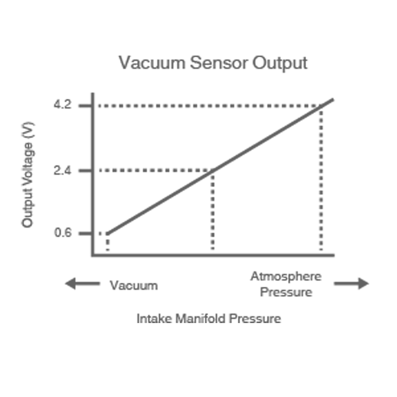
Pressure sensor
The Manifold Absolute Pressure sensor (MAP sensor) measures the pressure in the inlet manifold, providing instant manifold pressure information to the engine’s electronic control unit (ECU). The data from the MAP sensor is used to calculate air density and determine the engine’s air mass flow rate. The data from this sensor can be used for diagnostic purposes as it measures the throttle and turbo performance, as well as to diagnose unmetered air leaks in the inlet manifold.
Crankshaft and camshaft sensor
These sensors measure the speed and position of the cam and crankshaft. Their signal is processed by the engine management ECU to improve the accuracy of the ignition and fuel timing.
The two main technologies used in these sensors are typically of a hall or inductive type. The operations of these sensors are fundamentally similar.
Air mass/air flow meter
Its signal is used to calculate the injected fuel quantity, and for regulating the exhaust gas recirculation in diesel engines.
There have been several different types of sensor used over the years, depending on the systems vehicle manufacturers used. The two main types are air flow meters, or air mass meters. The terms air mass sensors and air flow meters are often used interchangeably. However, this is incorrect as the air flow meter only detects the air volume, whereas air mass sensors are significantly more precise because temperature and pressure are also taken into account.
Ignition coil
There are several design variations of the ignition coil and also, the technology used is dependent on a variety of criteria. Engine environment: temperature, installation, space allocated. Performance: Current supply requirements, ability to filter interference.
An ignition module has multiple ignition coils that are arranged in a common housing. The amount of coils depends on the number of cylinders an engine has; however these coils are functionally independent and operate like single spark ignition coils.
Double spark ignition coils generate two sparks per crankshaft rotation. The voltage is distributed so that the air/fuel mixture of a cylinder is ignited at the end of a compression stroke. The other cylinder’s ignition spark on the exhaust stroke is known as a ‘wasted spark’.
In pencil coils, each spark plug has its own ignition coil which is located directly above it. This design is modular and compact and is especially suitable, due to its space saving geometry, for modern downsized engines. This single ignition coil system supports misfire detection on both the primary and secondary winding. Any issues that occur are monitored and recorded in the engine control unit.
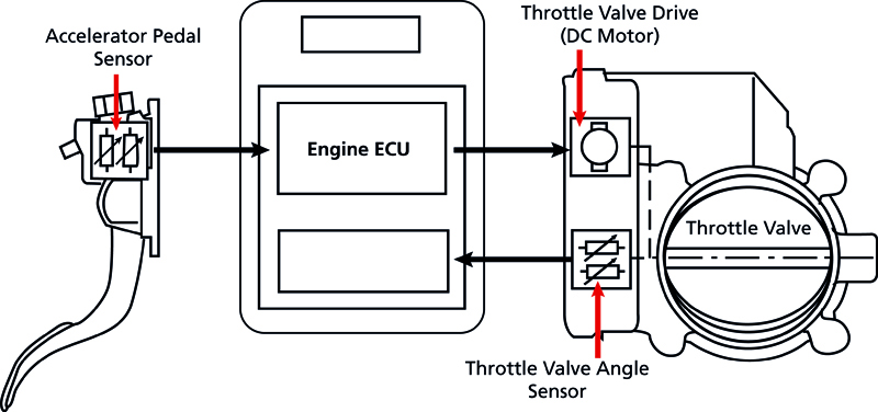
Throttle body
The engine management ECU has total responsibility for controlling the throttle valve inside the throttle body, with a DC motor to control the throttle valve angle. Feedback is then given to the ECU via a throttle position sensor. Together, these components make up the electronic throttle control.
The throttle control also plays an important role in emissions reduction, particularly in direct injection petrol engines when switching between homogeneous or stratified modes, as well as to control fresh air for the EGR.
All of these products and more are available in the febi engine management range. The range features over 3,300 engine sensors and actuators covering more than 60,000 European and Asian vehicle applications and provided in OE-matching quality.
What is OE matching quality?
febi rests its reputation firmly on the quality of the products provided to the automotive aftermarket. Every febi part is submitted to intensive and regular quality checking and electrical components are no exception.
Every part has been designed and manufactured to meet Original Equipment standards. With regular destructive and nondestructive testing, febi ensures a continued supply of quality products to the aftermarket.
The in-house quality control of febi electronic components is carried out with the help of a high-resolution X-ray machine. Its use ensures the non-destructive representation of the internal structures of parts with plastic coating as well as aluminium or thin-walled sheet steel housing. In this way the internal structure can be checked without damaging the product.


