Febi explains the science behind oxygen sensors.
5 wire wide band oxygen sensors are used on many engine control systems including diesels and direct injection petrol engines. They are designed to measure oxygen levels in the exhaust for air-fuel ratios between 8:1 and fresh air.
The main advantage of this type of sensor is to allow the engine control unit to determine how rich or how lean the mixture is, either side of lambda 1.
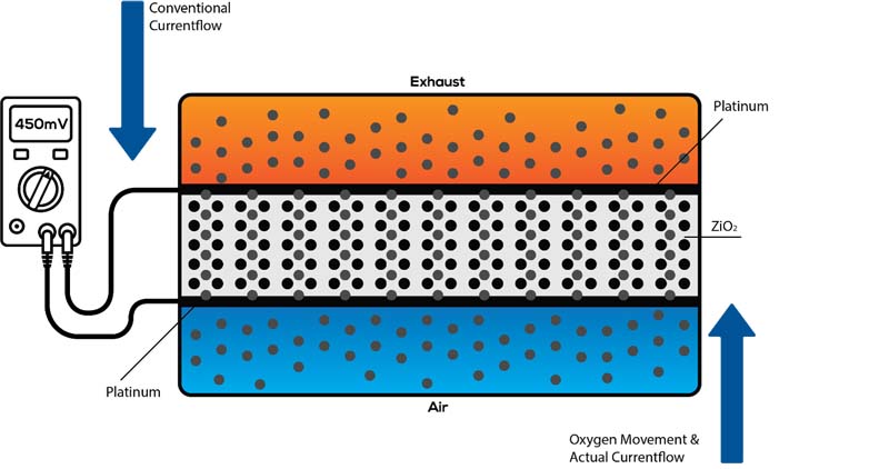
The sensor uses the same technology as most narrowband sensors. It relies on the property of Zirconium dioxide (ZrO2) to become a solid electrolyte at high temperatures. In a conventional narrow band sensor, platinum acts as a catalyst, dividing oxygen molecules (O2) into two oxygen atoms. Each atom then attracts two electrons to become negatively charged ions. The difference between the oxygen content in the exhaust gas of a spark ignition engine and the air, produces a potential difference (PD) which causes the oxygen ions to migrate through the ZrO2. The device is called a Nernst cell and is designed so that at lambda 1 (14.7:1), the potential difference is 450mV. A rich mixture increases the PD and weak mixtures will cause it to reduce. This is illustrated in Fig.1 (Main Image).
What’s inside?
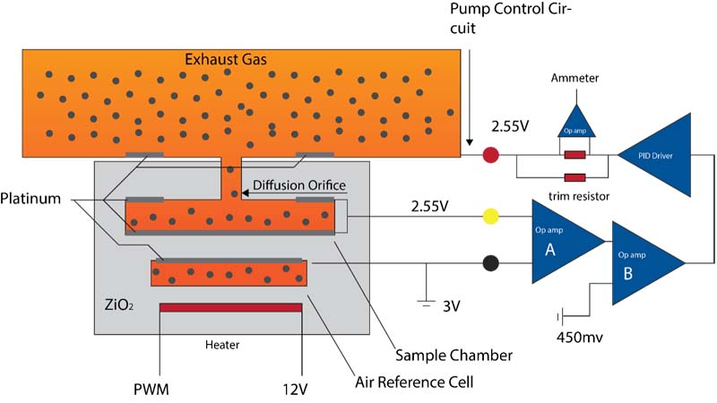
The sensor is made up from two Nernst cells. One cell measures the difference in oxygen levels between the air reference cell and the sample chamber, the other acts as a pump-topump oxygen into or out of the sample chamber.
By applying a voltage to the Nernst cell, oxygen can be pumped through the device. Reversing the polarity will change the direction of current flow and therefore the flow of oxygen.
The strategy of the control circuit is to maintain the first cell voltage at 450mV. This means that the oxygen content in the sample chamber represents that of a stoichiometric (lambda1) ratio. This is done irrespective of the oxygen content in the exhaust.
Operation
At Lambda1, the oxygen content in the sample chamber will cause the black-yellow Nernst cell to produce 450mV. The voltage will push against the 3V provided at the air reference cell to produce a voltage of 2.55V at the yellow wire. This is balanced by the pump control circuit. The two voltages are inputs to operational amplifier A (an op-amp outputs the difference in voltages of the two inputs). Op-amp A outputs 450mV. Op-amp B has one input of 450mV from a regulated supply, and 450mV from op-amp A. The output of op-amp B is 0V this condition is called stasis.
If the oxygen level rises in the exhaust (weak mixture), the oxygen level in the sample chamber will rise too. This is because oxygen molecules migrate into the sample chamber through the diffusion orifice (equalisation of partial pressures). This will cause the voltage generated by the blackyellow Nernst to drop, effectively the voltage pushes less hard against the 3V so the voltage at the yellow wire will start to rise. The inputs to op-amp A decrease in difference so the output of op-amp A falls. This means the output of op-amp B will rise above 0V. This triggers the PID driver to increase its output voltage. A current will now flow in the red-yellow Nernst. Conventional current flow will be from red to yellow, but actual electron flow will be in the opposite direction which pumps oxygen atoms through the ZrO2 out of the sample chamber, to bring the oxygen level back to that of stasis.
The current flow is relative to the oxygen content. The weaker the mixture, the greater the oxygen content, the higher the voltage at the red wire and the greater the current flow in the red-yellow Nernst cell. The current in the pump circuit is measured using a shunt resistor and op-amp. A trim resistor is fitted in the sensor to calibrate the sensor for manufacturing tolerances.
If the mixture becomes rich, the oxygen level in the sample chamber will start to fall. The black yellow Nernst cell voltage will increase pushing harder against the 3V. This causes the voltage difference across the Nernst to increase; consequently op-amp A outputs a negative voltage. The PID driver reacts by reducing its output voltage to lower than that of the yellow wire, causing the current to flow from yellow to red. Electron flow is in the opposite direction and, as a consequence oxygen is pumped into the sample chamber to bring it back to stasis.
There is normally no oxygen in the exhaust of a rich mixture, so oxygen is liberated from the carbon monoxide and carbon dioxide.
The heater circuit
The sensor has to keep a steady temperature of around 760°C; this is achieved by the heater circuit. The temperature is important because the resistance of the device changes with temperature. The heater is supplied with battery voltage and the earth is switched by the ECM using PWM. The temperature is monitored using a pulse on the Nernst circuit.
The current flow of the pulse is measured as a voltage drop, across a resistor and a simple ohms law calculation will give the resistance of the cell and thus the temperature. The PWM of the heater circuit is adjusted accordingly to maintain a stable temperature.
A faulty sensor can lead to a variety of problems, leading to increased fuel consumption and vehicle emissions.


