Since the introduction of the CAN (Controller Area Network) Bus in production cars in 1991, this technology has grown from luxury models to virtually all levels of vehicle today. In the past few years, aftermarket technicians have become more aware of this technology. Used as a means of intercommunication between ECUs, the CAN Bus has provided a simple means of connecting diagnostic tools to the vehicle via the standardised On Board Diagnostic (OBD) connector.
Whilst there are tools readily available for diagnostic connection to the CAN Bus, these tools do not always give the full picture of where problems may lie. Sometimes ‘Diagnostic Trouble Codes’ (DTCs) do not always get to the real source of the problem and there are many times where the DTC is not indicative of a problem with that ECU; this is a typical issue encountered from a CAN bus problem.
Here are some quick alternatives for checking for an unhealthy CAN Bus:
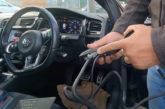
One step is to check the CAN bus with an oscilloscope. An overall bus check can be done via the OBD connector that is, in most cars, somewhere around the base of the steering wheel. Some imported cars will have the OBD connector in a similar area on the passenger side.
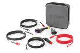
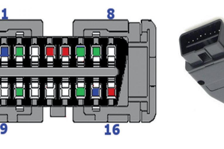
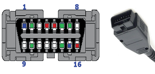
You can view the CAN electrical signals by connecting a two-channel oscilloscope to pins 6 (CAN_H) and 14 (CAN_L) of the OBD connector. Also ensure a ground connection is made at signal ground (pin 5). An OBD connector can be specially fabricated for this purpose.
The image (below, left) shows the pin connections on the vehicle side while the image on the right, shows a typical OBD connector case.
 PC-based oscilloscopes
Healthy CAN signal waveforms will appear as shown in the screenshot below. This is a typical view showing bursts of many CAN frames on the Bus – CAN_H is in red and CAN_L is in blue. PC-based oscilloscopes are used, as they are an inexpensive way to obtain an oscilloscope if you already have a laptop computer. A zoomed in view of a typical CAN frame and its data areas are illustrated in the capture at the bottom of the capture. Here you can see a close up view of the differential CAN_H and CAN_L signals. A good CAN frame will show the data transitioning from 2.5 V to 3.5 V for CAN _H, and from 2.5 V to 1.5 V for CAN_L.
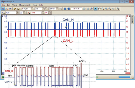 Oscilloscope view of healthy CAN Bus showing many CAN frames. The inset capture is the zoomed area of a CAN frame.
The capture below shows a CAN bus with a corrupted CAN_L signal. This is a real life situation from a 2004 Corsa and several DTCs were indicated on the fault code reader, which did not identify the correct source of the problem. Here it was found that the CAN_L connection at the ECM was faulty. If problems with the CAN Bus are quite drastic and communication is very noisy, one quick check that can be made is to see if the terminators are present. Access can be made at the OBD connector pins 6 (CAN_H) and 14 (CAN_L). Ensure all the power is off the vehicle and connect an ohmmeter to pins 6 and 14. Here you should read approximately 60 ohms – this is the equivalent of two 120 ohm resistors in parallel.
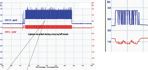 Standard CAN wave form at the Engine Control Module connector.
A standard CAN Bus will have a 120 ohm resistor termination at each end of the bus. This is required to avoid reflections that are caused by digital data communications. The resistors act as an “electrical shock absorber” and if they are not fitted correctly, the digital signals will “bounce” off the end of the data Bus, causing noisy reflections. This will have a significant effect on the performance of the CAN Bus.
If your reading is 120 ohms, this means that one of the terminations is missing. In a vehicle, terminators always reside in the ECUs at each end of the CAN Bus. If one is missing, this may indicate that one of the end ECUs is missing. If the resistance reading is a very high value (typically 10s of thousands of ohms), this indicates that there are no terminators fitted. This value is basically reading the input impedance of the ECUs. This is a drastic problem that will require the checking of connections at each end of the CAN Bus.
Diagnosis through simple tools
Here it can be seen that the use of a couple of simple tools can give indications of problems with the CAN Bus that fault code reader tools cannot always pinpoint. An inexpensive PC based oscilloscope, and a simple multi-meter using the ohmmeter option can give valuable immediate information on the health of the CAN Bus. There are simple Windows-based CAN analysis tools available that show the identifiers of the CAN frames along with the data field within the frame. The data fields can be interpreted to show the actual signals (rpm, temp, wheel speed, etc.). These tools can also give indications when errors occur on a CAN Bus.