The vehicle in question was a Peugeot 207 which had come from a well-respected Peugeot main dealership. The problem was described in some detail as a cylinder 4 misfire on load. I use the term ‘some detail’ here due to the extent of work that had already been carried out in an attempt to rectify the problem.
A new coil module and spark plugs were fitted to no avail, the cylinder head was removed and the valve seats were cut and lapped in. I later understood that the original hydraulic lifters and camshafts had also been refitted. Additionally the serial diagnostic code indicated: “significant misfire cylinder 4”.
The first thing to understand in this instance is that no. 4 cylinder is actually no. 1 to the rest Europe. The power plant is the wellproven and reliable kfu variant which, from a diagnostic point of view, offers good access to both ignition and fuel systems. The PCM is located next to the battery, with a simple slider plate allowing easy removal and enough free wiring to articulate it for ‘pin out’ testing.
Looking at the basics, a misfire can be caused by only three possible faults:
1. Ignition malfunction
2. Fuelling error
3. Mechanical defects
To simplify things further, it’s a combustion problem.
I begin with this approach on all problem jobs as a way of avoiding any prejudgement. It’s an easy trap to fall into as we all react to vehicle complaints by referring to past knowledge/experience and, ultimately, a problem like this can’t be that difficult… can it?
My advice is to take all information into account carefully and consider it in light of the fault, before then ignoring it; by doing so you guarantee not to miss the cause overlooked by previous technicians.
I began by checking the serial DTC’s – the MIL light was illuminated and flashing when the engine was running. This indicates a severe problem, with a risk of thermal damage to the catalyst. We always adopt the view that when dealing with spark ignition systems, in the absence of good ignition energy delivered to the plug electrode, good combustion simply can’t take place.
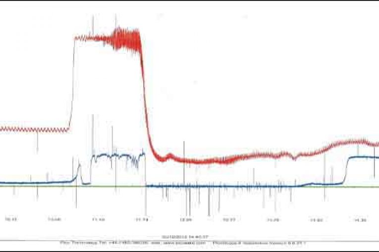
Starting my PicoScope evaluation, I took a look at the relationship between the Lambda and Map sensors as this would enable me to assess if the problem was an ignition or fuelling error. I focused on the acceleration load response, where I noted oxygen anomalies at/near the full load range – this confirmed ignition as the primary cause of the misfire. The Lambda signal, as expected, confirmed correct response throughout the fuelling range (see Fig 1).
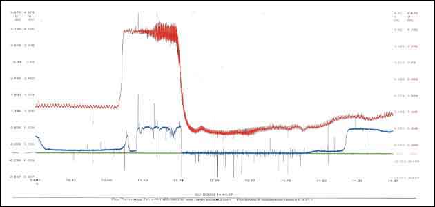
Fig 1. Oxygen error
The ignition system is a coil-per-plug type which uses a single cassette coil and allows easy access to a coil primary PicoScope evaluation. When testing the primary waveform pattern together with the current path profile I noted a poor burn time duration, on load, at no. 4 cylinder (see Fig 2).
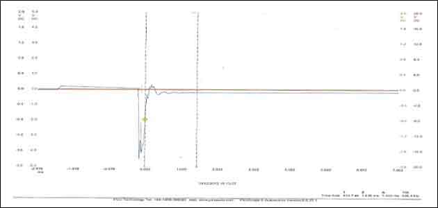
Fig 2. Burn error
The firing line voltage was high, confirming a high resistance in the ht firing line components. Noting that a new coil had previously been fitted and then removed for the original coil module, I decided to replace it with a genuine OE replacement.
The effect was immediate – a good burn duration of approx 1.8 ms with a peak current flow of 8A, together with a crisp throttle response. “There, I knew it wouldn’t be that difficult,” I said. Famous last words!
By this stage it was just about home time so I took the opportunity to undertake a road test. Drivability was excellent over some 4.5 miles of mixed conditions, yet worryingly when I embarked on the same journey the next morning the problem was as bad as ever.
Arriving back at the workshop I reattached the scope and to my surprise the burn time was not that bad; it’s worth noting that there is always a reduction in the burn time profile – especially when on load – and the current held steady at 8A.
Somewhat puzzled I decided to remove the coil module and attach the ht extension leads that come with the Pico ‘Advanced Kit’, before attaching the ht inductive lead directly to the secondary ht circuit.
It was at this point and, completely by chance, that I noted a discrepancy in the ignition energy delivered to the spark plug, by introducing a gap between the lead and plug. A discernible lack of energy was noticeable on cylinder no. 4 and also, to some extent, cylinder no. 1.
There was no way that this could’ve been due to the coil or the plug so it had to be down to the low tension circuit, however I’d already checked the peak current flow! Back to basics it was then.
The process of charging and discharging a coil is referred to as ‘inductance’ and the primary functionality includes peak current flow and speed of interruption. Re-checking the peak current flow confirmed a healthy 8A peak flow on all 4 primary circuits, however when examining the process of interruption a different situation became obvious.
When examining events like current interruption its likely you will need to choose a time base range in micro seconds – that’s over 1 millionth of a second!The interruption should be prompt and clean with minimal, if any, rounding or glitches as the current flow reduces. If this occurs it will drastically reduce the energy induced into the primary winding.
The cause
Looking at the scope readings (see Figs 3 and 4) I was able to identify that our vehicle was suffering with two driver stage problems and the cause of this was the worst case scenario – a leaky driver in the PCM.
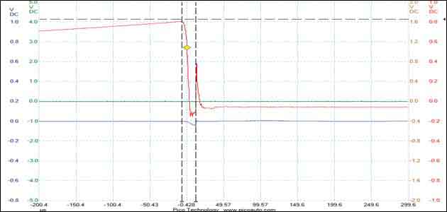
Fig 3. Coil inductance cycle error
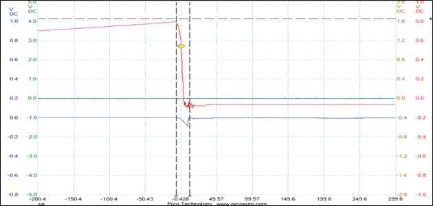
Fig 4. Good coil inductance cycle
In conclusion, it is essential to ensure that your ground references are sound from the outset as I understand that the overall cost of this repair to the customer ended up totalling around £700! It just goes to show that what appears on the surface as a simple misfire can sometimes be down to a very interesting cause.