Large numbers of the 2.0l common rail engine with the engine code CBDB are installed in various VW models. When the timing belt is changed, serious mistakes are often made. To ensure that changing the belts goes smoothly, ContiTech Power Transmission Group is providing mechanics with detailed installation tips.
When the timing belt is changed, the tension pulley, the idler pulley and the water pump should be replaced, too. Fitters require the following special tools for belt changing:
1. Locking pin for camshaft (OE 3359)
2. Locking pin for high-pressure pump gear
(OE 3359)
3. Arrester (OE T 10172, OE T 10172/4)
4. Lock ring tool for crankshaft (OE T 10050)
5. Cap wrench (OE T 10264)
6. Locking tool (OE T 10265)
Safety notes
Turn the engine in the direction of engine rotation ONLY on the crankshaft gear. The crankshaft sprocket and camshaft sprocket must never be rotated after the timing belt has been removed. Do not use camshaft locking tool(s) as an arrester when loosening or tightening the camshaft gear. When turning the camshaft, the crankshaft must not be positioned at top dead centre (OT) and the timing belt should not come in contact with oil or cooling water.
Adjustment work on the timing belt should only be carried out when the engine is cold. Make a note of the radio code and disconnect the battery’s negative terminal. We recommend that once the timing belt has been removed, it always be replaced and not reused.
Tightening torques
Self-locking nuts and bolts should always be replaced, even if not always specified by the manufacturer. According to VW, the following nuts and bolts are to be replaced:
■ Bolt(s) on the camshaft gear (tightening torque central bolt: 100 Nm, gear level 1: 20 Nm, gear level 2: 90°)
■ Bolt(s) on the high-pressure pump gear (level 1: 20 Nm, level 2: 90°)
■ Nut(s) of the tension pulley (level 1: 20 Nm, level 2: 45°)
■ Centre timing belt guard (10 Nm)
■ Lower timing belt guard (10 Nm)
■ Bolt(s) on the vibration damper (level 1: 10 Nm, level 2: 90°)
■ Idler pulley (50 Nm and turn an additional 90°).
Removal
Remove engine cover and dismantle fuel filter. Disconnect the plug on the coolant temperature sensor. Open clip(s) before removing the upper timing belt guard. Remove the front right wheel-house liner, drive unit belt, vibration damper, lower timing belt guard, centre timing belt guard and coolant pipe(s).
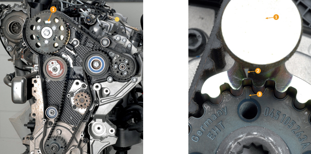
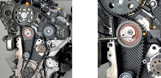
Position the engine at top dead centre of cylinder 1. Note the marking(s) (see first pic above, no. 1 and second pic above, nos. 2 and 3). The geared segment on the timing belt gear of the camshaft must be at the top (first pic above, no. 1). Use the lock ring tool for the crankshaft (OE T 10050) (second pic above, no. 1). The markings of the crankshaft and the lock ring tool for the crankshaft must align (second pic above, nos. 2 and 3). When using the lock ring tool for crankshaft, the pins must be positioned flush in the bore hole.
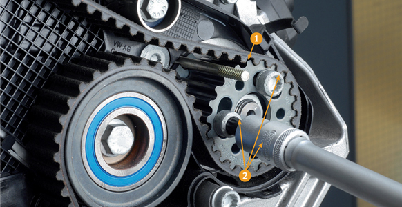
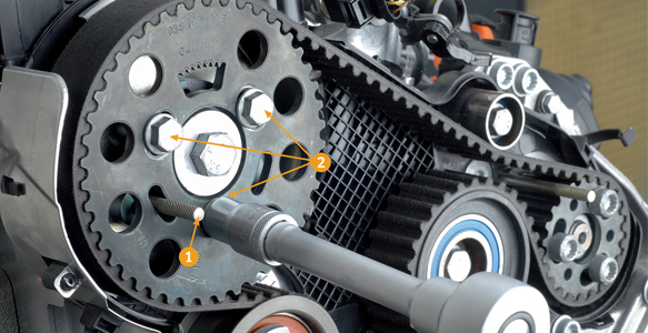
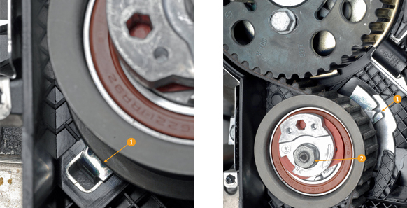
Use locking pins on the high-pressure pump gear and on the camshaft (pic above, no. 1 and pic below, no. 1). Loosen the bolts on the high-pressure pump gear (pic above, no. 2) before loosening the bolts on the camshaft gear (pic below, no. 2). Use the arrester and loosen the nut of the tension pulley (Fig 5, no. 1 and Fig 6, no. 1). Using the hex key, turn the eccentric of the tension roller (Fig 5, no. 3 and Fig 6, no. 2) anti-clockwise, until the tension roller can be disconnected with the special tool (Fig 5, no. 2).
Using the hex key, turn the tension pulley clockwise (max. load stop, Fig 6, no. 2), then tighten the nut of the tension pulley slightly (Fig 5, no. 1 and Fig 6, no. 1). Remove the timing belt from the idler pulley first and then from the gear wheels.
Installation
Adjustment work on the timing belt should only be carried out when the engine is cold. For the tension pulley, the nose of the base plate must be in the recess (Fig 7, no. 1). Check the top dead centre marking and re-adjust as required. The tension pulley must be locked using the locking tool and fixed to the stop on the right (Fig. 6, no. 2). Turn the camshaft gear, followed by the injection pump gear clockwise to the stop.
Position the timing belt onto the crankshaft, tension pulley, camshaft gear, coolant pump, and high-pressure pump, in that order. Loosen the nut of the tension pulley and remove the special tool (locking tool) before ensuring that the tension roller is positioned correctly. Using the hex key, turn the tension pulley clockwise (in the direction of the arrow). The pointer of the tension pulley must be flush with the recess in the base plate (Fig 8, no. 1), remembering that the nut of the tension pulley may not turn while this is being done (Fig 8, no. 2).
Tighten the nut of the tension pulley (Fig 8, no. 2). Hold the camshaft gear to maintain pretension anti-clockwise (use the arrester). Tighten the bolt(s) on the camshaft gear (Fig 4, no. 2) and on the high-pressure pump gear (Fig 3, no. 2) Remove locking pins on the high-pressure pump gear and on the camshaft pulley (Fig 3, no. 1 and Fig 4, no. 1) and then remove the crankshaft lock ring tool (Fig 2, no. 1). Rotate the crankshaft twice in the direction of engine rotation and position the crankshaft right before the TDC of the first cylinder (Fig 6).
Use the lock ring tool for the crankshaft (OE T 10050) (Fig 6, no. 1) and turn the crankshaft until the lock ring tool can be used. The pin on the crankshaft lock ring tool must be directly in front of the bore hole of the sealing flange (Fig 6, no. 1). Turn crankshaft until the lock ring tool can be used (Fig 6). Check whether the camshaft can be locked with the lock ring tool, remembering that the pointer of the tension pulley must be flush with the recess in the base plate. Tighten bolt(s) on the camshaft gear and on the injection pump gear.
In reverse
The rest of the installation procedure takes place as per the disassembly procedure, but in the reverse order. Mount the drive unit belt and decode the radio. Start the engine and check for proper functioning before reading the error memory. Carry out a test drive and document the timing belt change.