Sometimes we can be presented with vehicle faults that initially appear reasonably simple to diagnose and rectify. However, as Joshua Jones explains, if we take just a little time to check out what the car is doing to help us see the fault, then a more complicated fault that may rear its ugly head in the future can be easier to spot.
Last month, I took a look at a 2005 VW Golf TDI (BKC), as the owner had reported an MIL illumination and a general and fairly severe loss of power. The engine certainly seemed sluggish across all rpm and load ranges when tested, which usually gives me a bit of extra initial confidence as I know I will be dealing with a constant symptom as opposed to an intermittent one.
After my usual visual and audio inspection under the hood (everything looked in as much order as it usually does on a car that’s done 160,000 miles) I reached for the scan tool as the MIL was permanently lit and it seemed the next logical choice to achieve a quick correct diagnosis. Opting to read the three generic (P0 and P2) trouble codes first was a good choice as in this case they were very much related and led me promptly down a path to narrowing down the source of the fault. The codes logged in the ECU were P0489: ‘EGR system circuit-low, P2426: ‘EGR cooling valve circuit-low’ and P0047: ‘turbocharger boost control solenoid circuit-low’.
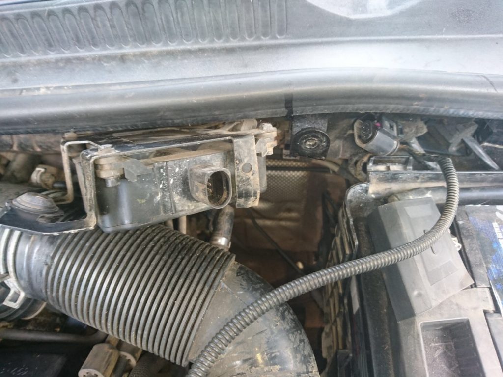
My first thoughts were that I was more than likely looking at a power supply problem because the DTCs were referring to three related components having less than expected voltage available in the circuit. On this particular vehicle, the EGR valve control solenoid and EGR cooling (vacuum operated) actuator control solenoid are integrated into one unit (along with the turbo control solenoid) and the box is secured to the bulkhead of the vehicle (see Fig 1). There is a fixing on one side of it that secures all vacuum lines and one multi-plug on the other with all electrical connections) so in this case in order to take traces of inputs and outputs I needed to refer to the engine management wiring diagram.
It clearly showed pins one, four and three of the six-pin plug as 12V power supplies for the three control solenoids in the box – the very same solenoids referred to in the trouble codes. After seeing the diagram, I knew that the only thing that directly links the three solenoids is the power supply, so I started there. After releasing the box from the bulkhead to gain access, I took voltage traces from these pins (still plugged in to make sure the circuit was loaded) with the key on and engine off. What I saw initially slightly confused me but then it became very clear.
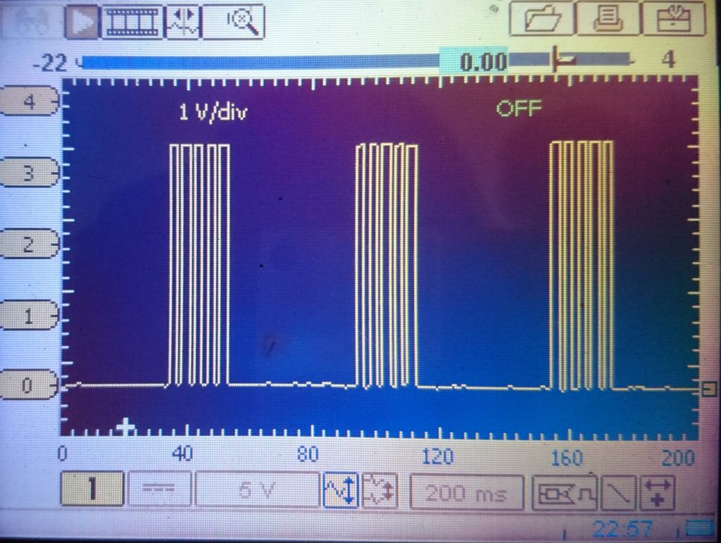
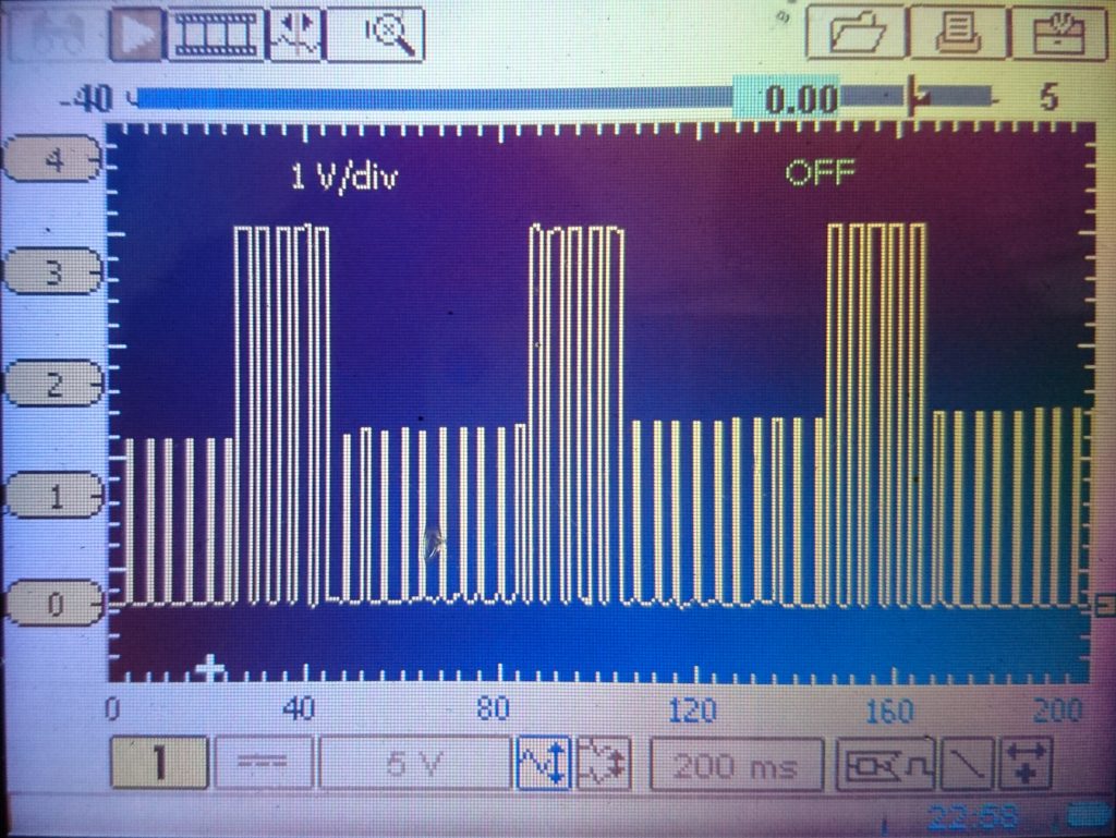
On all three pins I gathered the same waveform. This was a type of pulse width modulation that swapped every few seconds from five switches lasting around 20ms with a period of inactivity in between (Fig 2), to periods where smaller and varying modulations filled the gap (Fig 3). The peak output of this signal was around 3.5V, as shown. It transpired after exploring the signals from all six plugs that the same trace was found at all the terminals and if the same readings were taken with the plug disconnected, the signal was found at pins two, five and six and it dropped away from one, four and three, with these pins now being open circuit.
Now it made more sense. As pins two, five and six (as described in the wiring diagram) were the control side of a ground-controlled solenoid circuit, the signal was from the ECU. I was simply missing a power supply to these three solenoids. A quick return to the diagram showed that pins one, four and three were supplied by a control relay in the engine bay fuse box which in turn fed fuse 10 in the engine bay as well. I thought I would check the fuse first. On inspection, I was again initially confused as there was no fuse there.
I referred back to my trusty laptop for information on this fuse box and discovered that there was more than one fuse missing and it was a wonder that the car even ran! A quick call to the owner of the car was in order as I wanted to see if I got the answer to my question that I predicted I would get (anyone reading this article that has been in the trade a while will know exactly what the question was).
The owner had bought the vehicle with a failed turbocharger and had fitted a new unit. Since fitment, the vehicle had performed exactly as it did when it was presented to me, which had led the owner to believe that the fault was still turbo-related. On answering my question he explained that the previous owner told him that, before selling it, the cabin 12V power socket fuse (cigarette lighter fuse for older readers like me) had blown and it had been replaced. He then went on to explain that the MIL had promptly illuminated following on from this.
Now it made more sense. After spending some time returning fuses to their rightful homes, all was in order. I retook traces at the solenoid box multi plug to confirm power was available and indeed the traces looked very different. Pins one, four and three displayed a clean 12V power line and the control two, five and six showed a typical 0- 12V PWM. After deleting the DTCs and road testing, the MIL remained extinguished and the car glided along beautifully.
The point I was trying to make at the beginning of this case study is that the diagnosis of this fault was a simple one in the grand scheme of things (we all know how this is not always the case) but with the fuse missing, a window of opportunity for learning is opened thanks to the good old oscilloscope. With no power supply at the solenoids, the process used by the control unit in order to correctly identify its own problem (low circuit voltage) was nicely shown.
This signal would have been hidden if there was power to the circuit and the fault had lied with the solenoids themselves. It means that next time I experience a fault of this nature I will instantly know what I am looking at and what it signifies. If I had used a multimeter only to diagnose these symptoms or replaced components purely based on information from trouble codes, I would not have learned a little more about the way this particular control unit operates. It highlights that, although in this case the trouble codes had led me almost directly to the fault, there would certainly be cases where the initial diagnosis signal from the control unit that was shown could be manipulated by other factors if a different type of fault was experienced on that circuit – for example, a wiring fault.
Every time I take a trace from a car that I haven’t done before, I tend to learn something new. It’s an enjoyable and productive process.