What is a MAF sensor?
A Mass Airflow (MAF) sensor, also known as an “air meter,” measures the air coming into the intake system and transmits this information to the ECM.
The ECM utilises the MAF sensor output signal to precisely schedule fuel injection, creating an optimal air-fuel ratio. This results in reduced emissions and improved fuel economy, all while maintaining drivability.
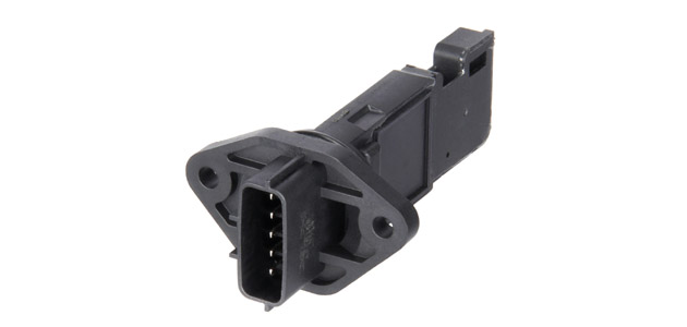
The MAF comprises of a pipe-shaped housing with flow rectifier, sensor protection and a sensor module screwed onto the outside. It is installed in the intake pipe between the air filter housing and the intake manifold.
MAF sensors can be installed in two ways: as a complete unit, including the flow tube, or as a probe-only design, which provides a greener, more cost-effective and often faster option.
How does a MAF sensor work?
There are two temperature-dependent metal film resistors attached to a glass membrane arranged in the air flow. The first resistor (RT) is a temperature sensor and measures the air temperature. The second resistor (RS) is used to record the air throughput.
Depending on the amount of air intake, the resistor RS cools down to a greater or lesser extent. In order to compensate the constant temperature difference between resistors RT and RS again, the flow through the resistor RS has to be controlled dynamically by the electronics. This heat flow serves as a parameter for the respective quantity of air intake by the engine. This measured value is required by the engine management control unit to calculate the amount of fuel required.
Why do MAF sensors fail?
Contamination is a key reason why MAF sensors fail and require replacement. As air, dirt and other debris gets into the sensor the parts become contaminated and fail. Drivers often notice sluggish performance, rough idling, poor acceleration or even stalling. There may also be a more frequent need to refuel.
Contamination could even occur as early as every 18,000 – 25,000 miles, depending on the vehicle model. For example, with small or compact cars, the MAF sensor can clog quicker, as it is placed in a smaller engine bay and subjected to more risk in critical areas (oil vapour flows and combustion debris). In this case, a replacement becomes the equivalent of a long drain oil service… it almost becomes a service-style repair.
A problem with the Mass Air Flow sensor often causes the “check engine” or “service engine soon” light in the vehicle instrument panel to illuminate. The “check engine” or “service engine soon” light comes on when the engine computer detects a fault in one of the components of the emission control system.
What to remember during MAF sensor replacement
It’s important to remember when selecting a MAF sensor for replacement that quality is critical. Using products of lower quality can: potentially reduce the life of and/or damage the catalytic converter; increase fuel consumption; experience poor response from the vehicle, causing drivability issues (lack of power); and breach regulating emission standards due to excessive smoking and increased particulate emissions.
Other common MAF sensor failure problems
■ Contact fault at the electrical connections
■ Damaged measuring elements
■ Mechanical damage (vibrations, accident)
■ Measuring element drift (exceeding the measuring framework)
Symptoms of failure
■ “Check engine” or “service engine soon” light is on
■ Hesitation/stalling on rapid acceleration
■ Poor engine running at idle and/or surge
■ Excessive vibrations when stationary
■ RPM’s changing noticeably without driver input
How to troubleshoot a MAF sensor – a technician’s checklist
1. Check the connector for a correct fit and good contact.
2. Check the mass air flow sensor for damage.
3. Check the measuring elements for damage.
4. Check the voltage supply with the ignition switched on (circuit diagram for pin assignment is necessary). Ref. value: 7.5 -14 V.
5. Check the output voltage with the engine running (circuit diagram for pin assignment is necessary). Ref. value: 0 -5 V.
6. Check the connection cables between the removed control unit connector and sensor connector for transmission (circuit diagram for pin assignment necessary). Ref. value: approx. 0 ohm.
7. Conduct an electronic test of the mass air flow sensor by the engine management control unit. If a fault occurs, a fault code is stored in the control unit and can be obtained using a diagnostics unit.