Tim Howes, Deputy General Manager – Supply Chain & Technical Service, NGK Spark Plugs (UK), looks at the origins of vehicle Lambda sensors and the various types.
The term Lambda is used to designate the value of the ratio of the mass of air supplied to an engine divided by the theoretical ideal requirement. That sounds very grand but, essentially, it means that if the engine is supplied with a fuel rich mixture it would have a Lambda reading of less than 1.0 Lambda. Alternatively, if it was supplied with a fuel lean mixture it would produce a reading greater than 1.0 Lambda. In most cases the basic function of a Lambda sensor is to ensure that the fuelling system supplies the engine with a mixture as close to 1.0 Lambda as possible.

Compounds from the use of leaded fuel can poison the Lambda sensor, slowing or preventing its operation
Why the need for a 1.0 Lambda mixture?
Most engines needs to be supplied with this 1.0 Lambda mixture because it is the ratio of fuel and air that produces the most complete combustion, thereby providing an efficient use of fuel. The resultant exhaust gases can be dealt with effectively by a three way catalytic converter. This theoretically ideal ratio is called a stoichiometric mixture and for a standard petrol engine the air/fuel ratio is 14.7:1 by mass.
Sensors achieve this control by measuring the residual oxygen content of the exhaust gas before it enters the catalyst; this is why Lambda sensors are also (and more correctly) known as exhaust gas oxygen sensors (EGO). An oxygen concentration outside certain limits will result in the sensor signalling the ECU to amend the fuelling system calibration, thus bringing the mixture back into acceptable limits.
Sensor variations
There are several different types of oxygen sensor in use but, for the majority of cars, there are two non-interchangeable sensor types, using a different strategy to detect the oxygen concentration in the exhaust gas.
Zirconia type
 This is by far the most popular sensor type. Under the protective metal end cap there is a thimble shaped ceramic element made from sintered zirconium dioxide. This has two thin micro porous platinum layers added: one covering the inside and one covering the outside. These layers are the electrodes to which the signal wires are attached. On top of the outer layer a further porous ceramic layer is added (aluminium and magnesium oxide) which protects the platinum from dissociation and erosion by the hot exhaust gases. The whole package is then fitted into a metal shell, part of which is threaded to allow fitment to the exhaust system.
This element is inserted into a convenient part of the exhaust system up-stream of the catalyst. The heat energy imparted by the exhaust gases will raise the temperature of the sensor. When 300°C is reached the Zirconia ceramic has a special property in that it becomes ‘permeable’ and will allow oxygen ions to pass through it. The centre of the thimble shaped ceramic element is hollow. This is to allow a pocket of ambient air to act as a reference gas.
In theory a stoichiometric combustion gas will have no oxygen present, however, in practice, small levels of oxygen are present. In an attempt to maintain equilibrium, oxygen ions will migrate through the permeable ceramic and platinum layers. The movement of these ions causes a voltage to be generated. Put simply, the sensor behaves like a small battery with the Zirconia acting as the electrolyte. In this way the voltage output is relative to the oxygen concentration in the exhaust gas.
Lean air fuel mixtures result in relatively small amounts of ionic movement due to the oxygen rich 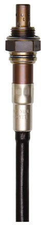 environment of the exhaust gas, whereas rich mixtures are deficient in oxygen, resulting in larger ionic movement as the sensor tries to achieve equilibrium across the element.
Around the stoichiometric point (1.0 Lambda) there is an abrupt and dramatic change in oxygen concentration, producing a large differential between exhaust gas and the reference air. This in turn produces a relatively large change in voltage. This voltage is the signal which is sent to the fuelling control system, enabling an adjustment to bring the air/fuel ratio back into the acceptable window around 1.0 Lambda. There is a natural tendency for the fuel system to overshoot the desired window, therefore the voltage output cycles – fuel lean/fuel rich between a minimum and maximum value – nominally between 0.1 V ~ 0.9 V. This occurs with a frequency of 1~2 Hz. If a gas analysis is carried out the reading may fluctuate between 0.9 Lambda and 1.1 Lambda.
Because the sensor has to reach 300°C before it starts to function there is a period after start up which is not controlled by the Lambda sensor. To combat this it is desirable to install the sensor as near to the engine as is practical. Under certain conditions exhaust gas temperatures can drop sufficiently to impair the function of an unheated sensor. A solution to both problems is to use a heater inside the sensor which rapidly brings the ceramic up to temperature. Heated sensors (HEGO) are therefore particularly desirable when trying to reduce noxious gas emissions. Most contemporary engine control systems are designed to work with heated sensors.
Titania type
The less common Titania sensors have a similar appearance but work in a different way. They use a layered titanium dioxide ceramic element with its electrodes sandwiched in between. At a critical point around 1.0 Lambda the Titania ceramic possesses the property whereby its electrical resistance changes substantially. If a small voltage is applied (typically 5 V) by the vehicle’s control system this change in resistance can be used to adjust the fuelling, keeping the exhaust gases within the desired limits. These sensors do not need access to ambient reference air.
Titania sensors are more expensive to produce but reach operating temperature faster, reaction times are faster and they can be made physically smaller. The sensor’s ceramic element requires a high degree of protection. This is provided by the metal end cap which has specially designed holes to allow a good flow of exhaust gas whilst preventing impact damage, water splash and extremes of temperature. Total protection against leaded fuel and some other air borne compounds can’t be provided, however. These unfriendly compounds can poison the sensor, slowing or preventing its operation.

Special types
There are some systems that allow the engine to run on considerably leaner mixtures under certain conditions and these require a special type of oxygen sensor called a ‘wide band’ or ‘broad band’ sensor. These are much more complex in operation with very sophisticated control mechanisms.
In addition, most road vehicles also have a second sensor fitted after the catalyst. This functions in the same way but is used to monitor the effectiveness of the catalyst and is often referred to as the CMS (catalyst monitoring sensor) or diagnostic sensor; this usually plays little part in regulating the fuelling system but can, on some applications, detect catalyst ageing and allow calibration changes to accommodate.
Tim Howes