KTS diagnotics made ‘ESI’ from Robert Bosch.
This regular series of technical articles from Bosch focuses on how to get the best out of its ESI[tronic] 2.0 software, which is used in conjunction with the KTS range of diagnostic tools for vehicle fault diagnosis and service function procedures. Because of the vast range of features available through the software, Bosch’s technical team will be breaking things down into bite-sized chunks, starting at a beginner level and progressing through to more advanced functions.
In the previous column we covered System Overview and the excellent Protocol report features in Bosch ESI 2.0, which allow you to not only check the complete diagnostic state of a vehicle but also to produce a professional report of all the relevant functions and data to present to the customer. This time around we’ll go through the Service Information System (SIS) and ‘Trouble-shooting’ functions of the tool, which are the ‘crown jewels’ of ESI 2.0 and Bosch automotive diagnostics. We‘ll show you how to get the best results from SIS using the Bosch KTS to help you to understand automotive components and systems and, in many cases, fix them first time.
The SIS trouble-shooting function of ESI 2.0 consists of both a database with extensive Bosch technical content and a direct interface to the multi-meter and diagnostic tester within the KTS unit. By using this system correctly it will reliably guide you, step-by-step, from detecting the symptoms of a problem and any associated diagnostic trouble codes, to the cause of the fault and then on to the rectification of the problem on the vehicle. In most cases all of the information required for fault finding, maintenance and routine service tasks is available on the tool in the hands of the technician.
The amount of data available in ESI 2.0 is dependent upon the subscription level held by the user. The two main ESI subscription types for car and LCV applications are the ‘Diagnostics package’ which has the full features of Serial Diagnosis (SD) and Service Information System (SIS) trouble-shooting.
You then have the ‘Master package’ which also comes with vast amounts of inspection and maintenance data, comfort systems circuit diagrams and technical service bulletins.
On the vehicle, when you read the error memory of an ECU and there are fault codes present you will see the DTC number, description and the status of the fault code – for example, whether it is static or sporadic and often applicable freeze frame data as well. The ‘Instructions’ F8 soft key appears at the bottom centre of the screen when there is a trouble-shooting guided repair instruction available for that DTC and system.
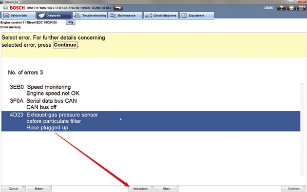
Clicking ‘Instructions’ takes you straight into the trouble-shooting tab and the guided fault finding and repair instructions for all of the data that Bosch has associated to that particular fault code. The first page of the guided help info gives you a list of other possible related fault codes and a ‘Show additional information’ link at the top of the page guides you to the functional description of the component to be tested – whether it’s a sensor or an actuator.
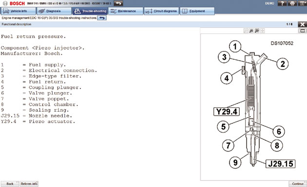
This could be several pages long and is really useful if you need to know what type that particular part is or how it works and what it is responsible for. This type of information can help you to better understand the system you’re working on and demonstrates the benefits of ESI 2.0.
When you’ve reached the end of a chapter a confirmation pop-up box appears, asking if this section has been processed. Clicking “Yes” returns you to the original page and a green tick is put through the ‘Functional description’ link button.
This helps you to keep track of the progress of the job, especially if you’re interrupted at any point in the process. Also the confirmation adds an entry into the protocol log (if configured) that we covered in the last issue. Wherever any soft key icon buttons are shown in the instructions you can hover your cursor over the button for a ‘tool tip’, to confirm what that button will do.
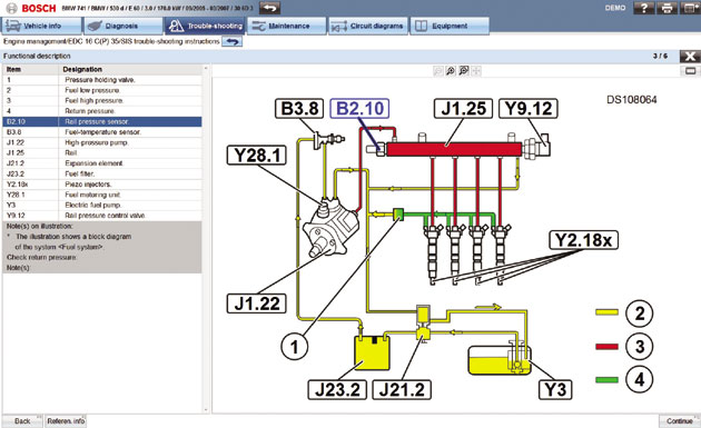
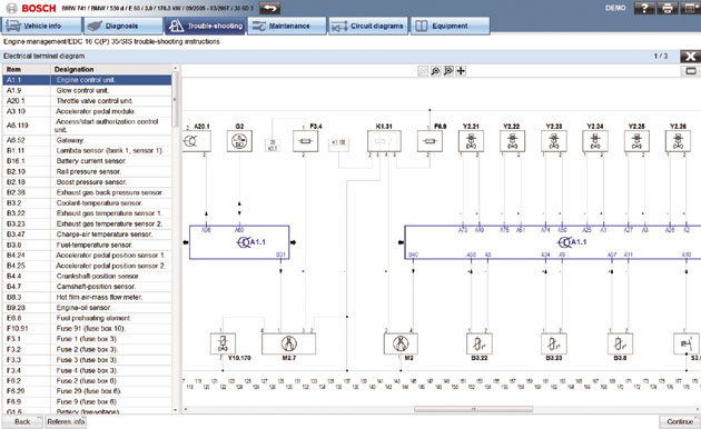
Clicking ‘Continue F12’ will take you to the next page which usually gives you a picture or a diagram of the wiring connector for the component in question and a test plan to check the power supply, ground connection and signal wires.
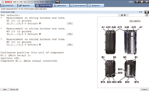
The required pin assignments and test conditions will be clearly shown as well as the expected value range if all is well. The ‘Read measured value’ button can be pressed to ‘pop up’ the multi-meter function of the KTS 540 or 570 for a real time measurement.
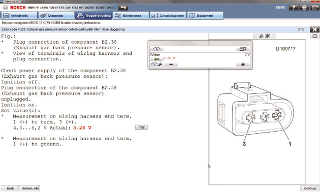
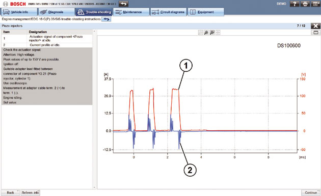
The detailed instructions will guide you through the process of a complete test plan by checking the relevant values that are critical to successful operation of that component or circuit. Oscilloscope analysis may be necessary, in which case the test connection set-up and correct waveform profile will be shown on the screen.
If by this time you’ve not managed to pinpoint the problem and find the cause of the fault, the instructions will also contain a list of other possible defects to be checked. This whole process should help you through the job from beginning to end and obtain the correct diagnosis of a fault on the vehicle which should lead to a first-time fix.
The usefulness and capabilities of the Bosch ESI 2.0 trouble-shooting instructions extend much further than this, in fact we’ve only just scratched the surface!
ECU selection
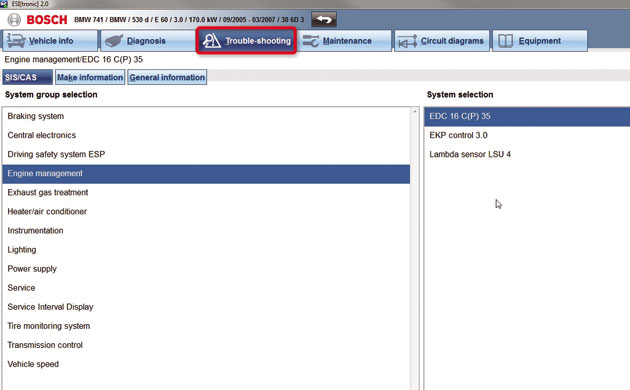
You don’t have to enter the guided help files from the instructions button of a fault code to find the information. Maybe the vehicle has a problem and there are no DTCs stored. In this case you can click straight onto the main trouble-shooting tab along the top of the screen and select an ECU from the system group selection list for which you want to find out information. This data can also be accessed if the car isn’t present but you want to research the system.
The menus of the trouble-shooting repair instructions generally follow the same format and layout, whichever vehicle or system you’re looking at. Again, this brings familiarity to the use of the tool and helps you to work smarter and more efficiently by finding the right information fast when fault-finding. A latest feature on the ESI 2.0 is a direct link from the comfort system circuit diagram schematics to the SIS powertrain and chassis circuit diagrams. Previously, the two sources of circuit diagrams for the vehicle were in different locations. Now with the 2015/3 software update customers who subscribe to ‘Master package’ will be able to view and access a complete list of schematics included in ESI 2.0 within a single list in the ‘Circuit diagrams’ tab, making the system easier to navigate.
The Bosch trouble-shooting information covers many topics for each system including: safety measures, special tools, descriptions, guided trouble-shooting, CAS[Plus] interface links to the serial diagnostic functions of KTS, wiring diagrams, ECU connector pin assignments, component position, removal and installation instructions and diagrams, to name but a few. We suggest, if you haven’t experienced Bosch ESI 2.0 already, that you have a look yourself. You might be surprised!
Keep a look out for the next instalment!