A full clutch replacement guide for a Toyota RAV4 2.0 D4D from the experts at Schaeffler Automotive Aftermarket.
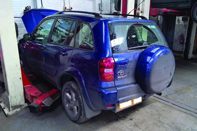
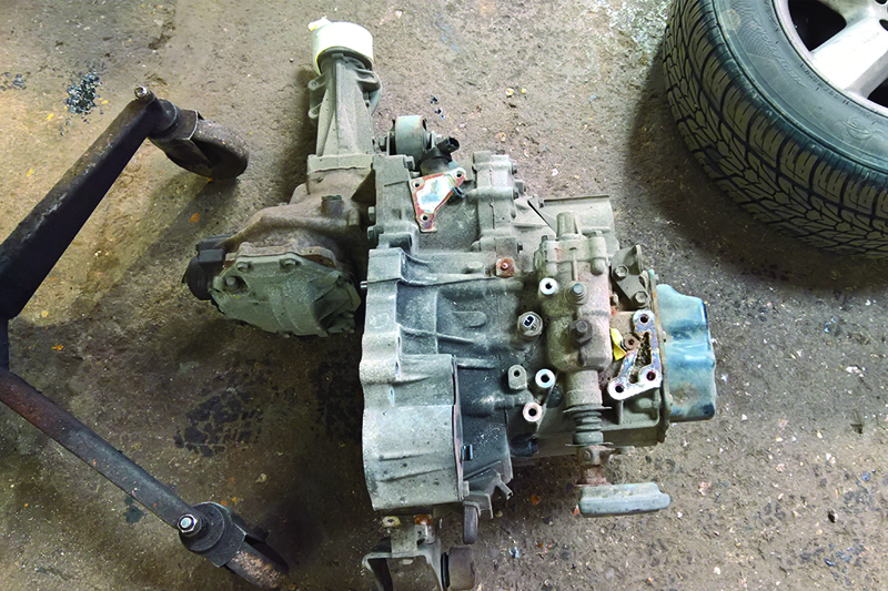
In this month’s article, we are replacing the clutch and Dual Mass Flywheel (DMF) in a Toyota RAV4 2.0 D4D with permanent four-wheel drive, which has covered more than 130,000 miles. The customer reported that the clutch slips under full load, which a quick road test confirmed, and clutch replacement was advised.
Toyota released the first generation RAV4 in 1994 – RAV standing for Recreational Active Vehicle. Design features included increased interior room, higher visibility and the option of permanent four-wheel drive, along with good manoeuvrability and good fuel economy, all in a compact vehicle.
Toyota’s current RAV4 is the fourth generation. The RAV4 is available in short or long wheelbase with petrol or diesel engines, in either two-wheel drive or permanent four- wheel drive, and it also shares the same platform as the Toyota Carina and Corolla.
For this repair, we used the following workshop equipment: a two-post ramp and two transmission jacks.
If the vehicle is equipped with locking wheel bolts, ensure you have the key/tool prior to starting the repair.
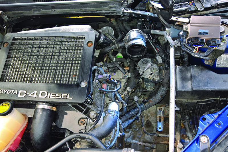
With the vehicle placed on the ramp, disconnect the battery, then disconnect the multiplug from the air flow meter and remove the complete air filter assembly (see below) and disconnect the reverse light switch multiplug and the gearbox earth cable.
Now remove the gear linkage assembly and then unbolt the clutch slave cylinder that is located on the front of the gearbox, retained by 2 x 13mm nuts, and stow safely (the hydraulics do not have to be disconnected). You’ll also need to remove the plate that is mounted with the slave cylinder. At this point, we can remove the top bell housing bolts and then slacken the top gearbox mounting ready for removal later.
With the vehicle on the floor, slacken the wheel bolts and the O/S/F hub nut, raise the ramp to waist height and remove both front wheels, the O/S/F hub nut, the N/S/F wheel arch splash guard (see below) and the N/S/F under tray.
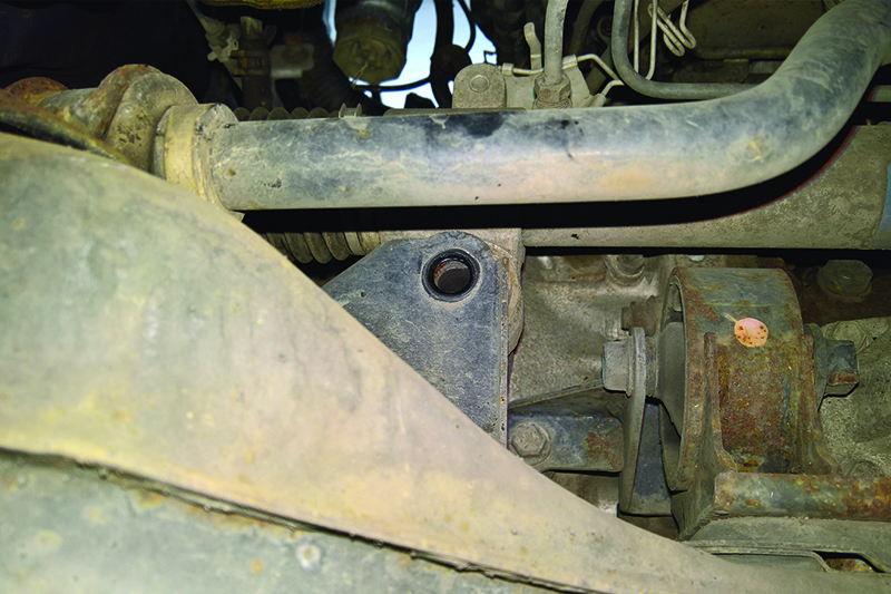
Raise the vehicle. Now we need to remove the front sub-frame, so disconnect the anti- roll bar clamps, remove the front gearbox mounting, disconnect both bottom ball joints, and take out the two bolts that hold the steering rack to the front sub-frame (see below) and secure the steering rack to the engine bay to hold in place.
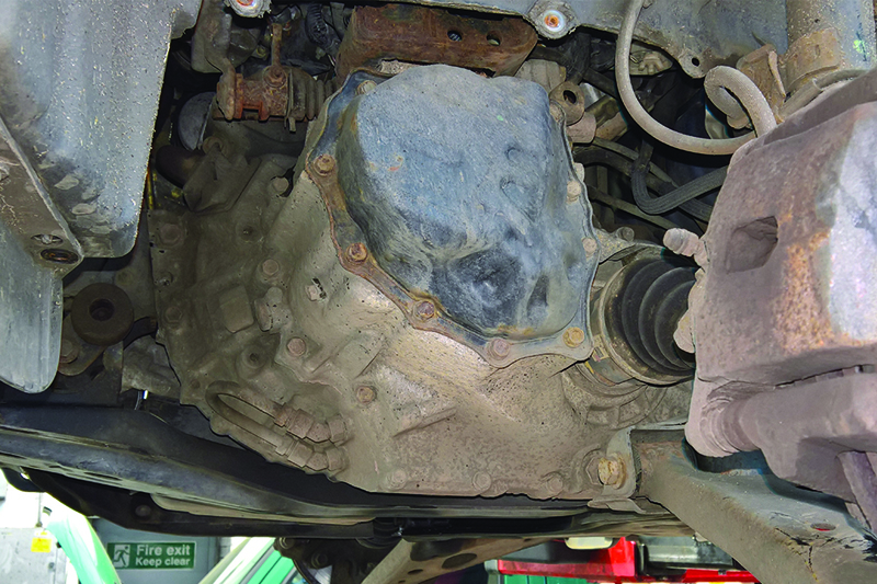
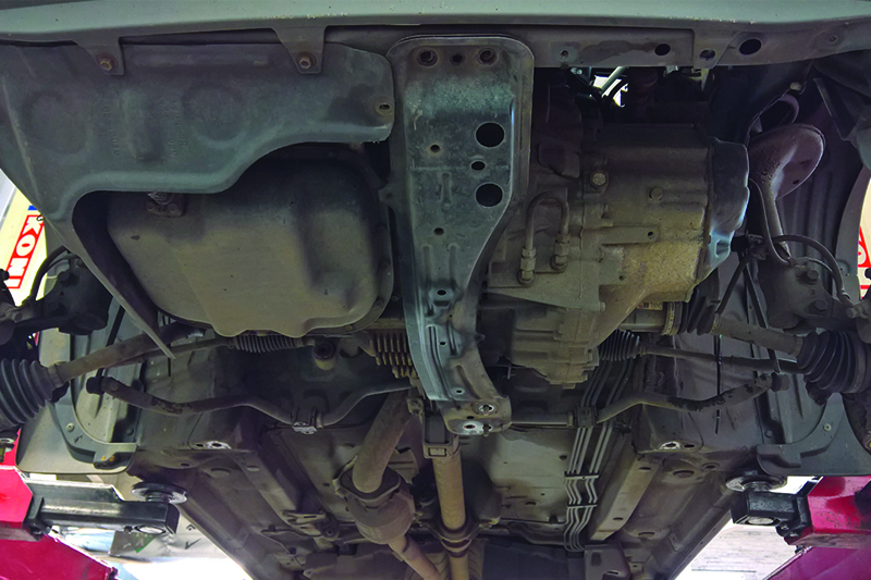
Support the front sub-frame with a transmission jack and remove the sub- frame retaining bolts, lower the transmission jack and remove the front sub-frame (see below) and then remove the gearbox cross member/cradle.
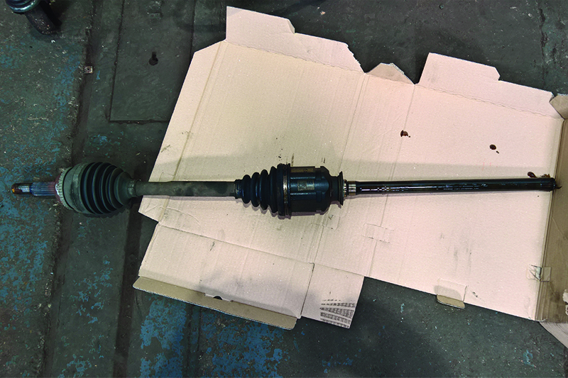
Now drain the oil out of the gearbox and transfer box and, once the oil has drained, remove the O/S/F driveshaft by sliding out of the transfer box and store in a safe and clean area (see below).
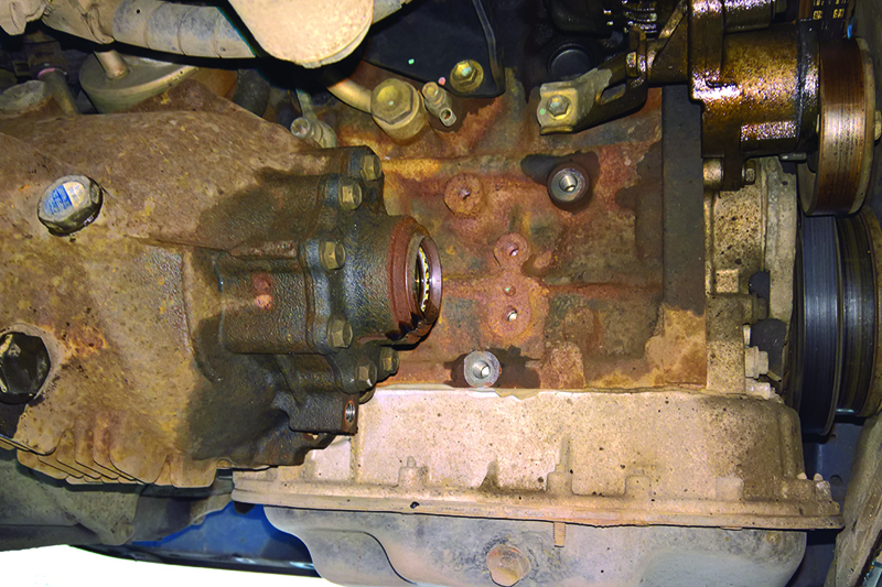
It is advisable to plug the driveshaft holes when the driveshafts have been removed, to stop any excess oil dripping and to stop anything going into the transfer box, then the support bracket for the transfer box to the engine can be removed (see below).
The engine and gearbox can now be eased forward to release the front prop shaft joint from the transfer box. Next, pull the bottom of the N/S/F strut assembly outwards which will release the N/S/F driveshaft from the transfer box and the driveshaft can then be positioned conveniently.
From under the vehicle, we can now remove the gear linkage bracket and the speedo cable, which are located towards the top rear of the gearbox. Disconnect the starter motor from the front of the engine and leave in position. Support the engine using an engine brace or transmission jack, from the top, and disconnect the top gearbox mounting from the gearbox.
Now remove the remaining bell housing bolts, leaving one to hold the gearbox in position. Support the gearbox with a transmission jack and cradle, remove the final bell housing bolt and ease the gearbox away from the engine. You might find that the gearbox has seized on the dowels, so if this is the case, work the gearbox up and down until it has released from the dowels and then remove the gearbox (see below).
With the clutch now accessible, it was removed and inspected, with evidence that it had reached the end of its service life and that ‘slipping’ had taken place. The customer also requested that the DMF be replaced at the same time.
With the clutch and flywheel removed, clean the back of the engine to remove any clutch dust that could contaminate the new clutch and flywheel assembly, check all parts are correct and then fit the new flywheel.
With the flywheel torqued, clean the bell housing of the gearbox and clean and check all moving parts and pivot points for wear, and replace if required. Apply a small amount of high melting point grease to pivot points and contact areas and re-assemble removing any excess grease.
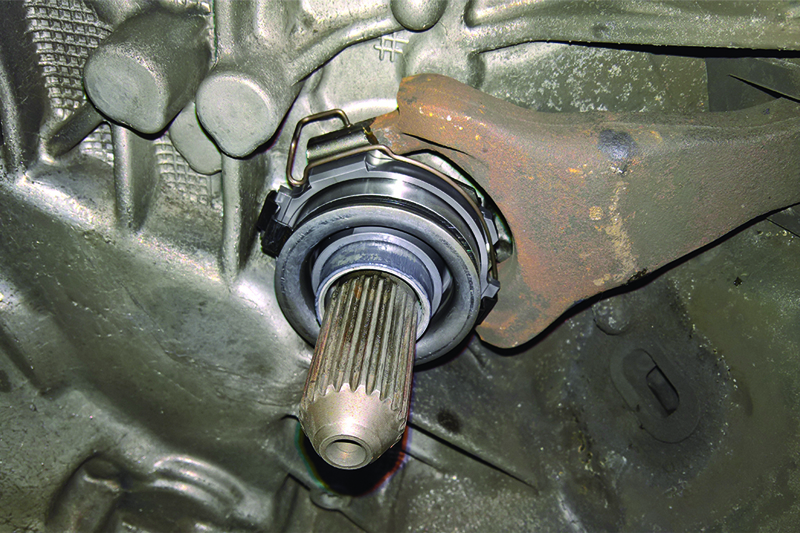
Install the new release bearing (see below), then lightly lubricate the gearbox input shaft splines with high melting point grease and slide the new clutch plate onto the input shaft to evenly distribute the grease, and to ensure the clutch plate is correct, wipe off any excess grease.
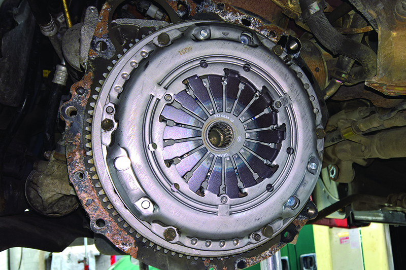
Fit the new clutch to the flywheel using a clutch alignment tool, ensuring the clutch plate is positioned correctly with ‘Gearbox Side’ or ‘Getriebe Seite’ facing the gearbox and then tighten the clutch bolts in an even and sequential manner and torque to the manufacturer’s specification (see below).
Re-fit the gearbox in reverse order of removal, refill the gearbox and transfer box with the correct quantity and specification of oil and, after connecting the battery, reset all electrical items as required and carry out a road test to ensure the repair is complete.