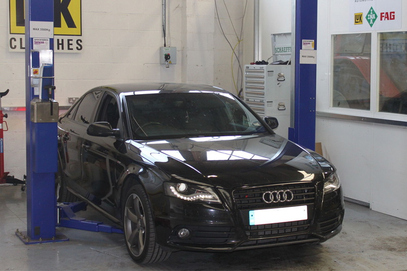
A full clutch replacement guide for a 2.0 TDI model from Schaeffler Automotive Aftermarket UK.
Audi released the 8K chassis A4 in 2007. Included in this model were some changes to the clutch and transmission system with the wheel base increased, but not the overall length of the car.
This was achieved by moving the front running gear forwards and also moving the front differential 152mm from behind the clutch assembly to the side of the clutch assembly and then using a flange shaft that passes through the drive plate/flywheel assembly to connect the drive from the differential to the N/S/F drive shaft (see below).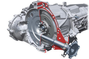
The new configuration Audi – called Modular Longitudinal Platform (MLP) – is used on all current Audis with a longitudinal engine and gearbox configuration. On initial inspection, a clutch replacement can look like a complicated repair, but with a little know- how this will prove to be an ideal job for any independent garage.
RECOMMENDED LABOUR TIME: 7.5 HOURS LUK CLUTCH FITTED: 624328500 LUK DMF FITTED: 415034410
Biting point
The customer’s concern was that the clutch pedal’s biting point was very high. After a short test confirmed this a clutch replacement was advised and the customer also requested that the dual mass flywheel (DMF) was replaced. The workshop equipment required for the repair is a two-post ramp, transmission jack and a universal clutch alignment tool.
With the vehicle placed on the ramp, disconnect the battery located in the boot under the spare wheel – don’t close the boot, however, as this has an electric release system. You should also make sure the steering lock has actuated as you have to disconnect the steering column before raising the vehicle and removing the engine and gearbox undertrays (see below).
Remove the transmission tunnel bracing frame, taking care to disconnect the pipe bracket and heat shield, then remove the pinch bolt from the steering column universal joint/steering rack, the exhaust front pipe bracket and also the small o/s heat shield that is fixed to the chassis leg and front sub-frame.
Disconnect the o/s driveshaft from the gearbox flange by removing the six bolts, then remove the inner driveshaft joint heat shield from the gearbox, held by three Allen bolts. Now disconnect the n/s driveshaft from the gearbox flange and remove the small n/s heat shield from the chassis leg and sub- frame (see below). 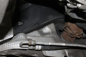
Remove the three bolts from the driveshaft/flange shaft retaining plate and ease the flange shaft out 25mm so it’s ready for removal. Disconnect the electrical multi-plug from the steering rack, remove the four nuts that hold the anti-roll bar clamps to the sub-frame and allow the anti-roll bar to hang down (see below).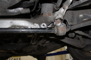
Remove the two bolts that mount the steering rack to the front sub-frame, ease the steering rack from the sub-frame and allow it to hang – this gives you access to the starter motor bolts. Slacken the exhaust sleeve that connects the intermediate pipe to the rear exhaust section and part the exhaust, allowing the intermediate section to hang down. Support the back of the gearbox with a transmission jack and remove the rear gearbox mounting. Now remove the clutch slave cylinder bolt and ease out the slave cylinder before stowing.
Remove the three bolts from the front engine mount to allow a little tilt on the engine to aid gearbox removal. Tilt the gearbox down for access to the top of the gearbox. Disconnect the gear linkage and stabiliser bar and also the two electrical multi-plugs from the gearbox. There is a third multi-plug that is located in a bracket on the top of the gearbox which requires the plug and wiring to be removed from the bracket and the multi-plug to be disconnected.
Remove the black plastic blanking plate located at the bottom of the bell housing to gain access and then remove the three flywheel-to-drive-plate bolts (see below). 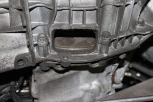
Start to remove the bell housing bolts, leaving a couple of accessible bolts until the gearbox is supported and ready for removal; good practice is to store the bolts in the position/pattern of removal.
The bell housing bolts have a twice torque life so always mark the heads of the bolts with a centre punch to indicate that they’ve been torqued for a second time and will require replacement if removed again. Also note that the top starter motor bolt has a spacer located between the bell housing and the starter motor.
Position the gearbox jack ready for gearbox removal, and secure the gearbox to the transmission jack (see below).
Now remove the final bell housing bolts and ease the gearbox back. When the gearbox is free from the engine remove the flange shaft from the gearbox by sliding it out between the chassis leg and front sub-frame towards the n/s wheel. Remove the driveshaft and store.
Carefully remove the gearbox from the vehicle and lower. Now take the black handle tool in the clutch kit and secure it to the flywheel (see below) before carefully removing the heavy flywheel and clutch assembly. The release bearing, arm and sleeve can now also be removed. Check for any wear on the release arm pivot points and replace if required.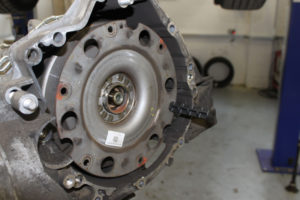
Using high melting point grease, lightly lubricate the pivot points on the release arm and replace the input shaft sleeve and release bearing. Lightly lubricate the input shaft splines and check the clutch plate fits the splines, wiping off any excess grease.
Assemble the new clutch and DMF using a clutch alignment tool, ensuring that the driven plate is fitted correctly. When bolting the clutch pressure plate to the DMF tighten the bolts evenly and sequentially. Before installing the clutch and flywheel assembly to the gearbox, check that the three small yellow springs for the self-adjusting clutch are still compressed. Now support the clutch and flywheel using the tool from the clutch kit (see below).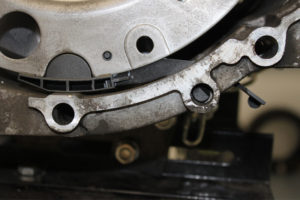
Check that the dowels are still located in the engine and then install the gearbox, remembering to insert the flange shaft before locating the gearbox on the engine. With the gearbox and flywheel located, remove the clutch/flywheel support tool, refit the accessible bell housing bolts and tighten. The transmission jack can be removed and used to support the rear of the gearbox and the remaining bell housing bolts installed. Rotate the flywheel to align the flywheel to the drive plate holes, insert the new bolts supplied and tighten/torque. Refit all other items in reverse order of removal.