A full timing belt replacement guide for a 1997 Opel Omega B, 2.5L V6 with engine code X25XE from Contitech
When the timing belt is replaced, serious mistakes are often made. To ensure that the belts are replaced without any problems, ContiTech Power Transmission Group is providing fitters with detailed installation tips. In this bulletin, the manufacturer demonstrates how mistakes can be prevented when using timing belt kit CT884 K1. The timing belt is labeled with guide marks and with the direction of travel. Please note: A timing belt offset of just one tooth can cause engine damage.
Tip: When the timing belt is changed, the V- ribbed belt should be replaced as well. The V- ribbed belt must therefore be replaced at the same time, so as to prevent subsequent failures incurring unnecessary costs. If, however, the old V-ribbed belt is to be re-installed, mark the direction of travel before removal.
- Lock ring tool for crankshaft OE (KM-800-10)
- Retaining tool for camshaft OE (KM-800-1) red
- Retaining tool for camshaft OE (KM-800-2) green
- Inspection gauge OE (KM-800-20)
- Chock OE (KM-800-30)
- Chuck key OE (MKM-6038)
Preparatory work:
Identify the vehicle using the engine code, then disconnect the vehicle’s battery. Do not turn the crankshaft or camshaft when the timing belts have been removed. Turn the engine in the normal direction of rotation (clockwise), if not otherwise specified.
Turn the engine only at the crankshaft gear and not at other gear wheels. Only complete testing and adjustment tasks when the engine is cold. Do not allow the belts to come into contact with damaging materials such as engine oil or coolant.
Never remove the timing belt without using the retaining tools to set and fix the engine at TDC position.
Removal:
Set the control times at the TDC marking of the first cylinder. Turn the engine using the crankshaft until the TDC marking on the camshaft gears is just before TDC (Fig 1).
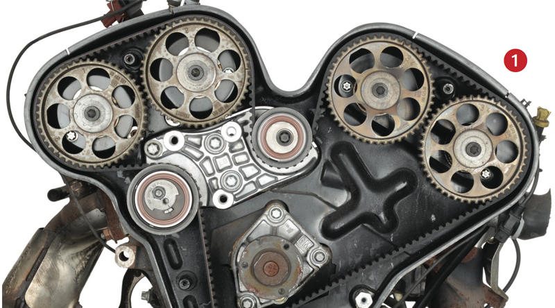
The notches on the camshaft gears must be located just in front of the grooves in the rear timing gear guard.
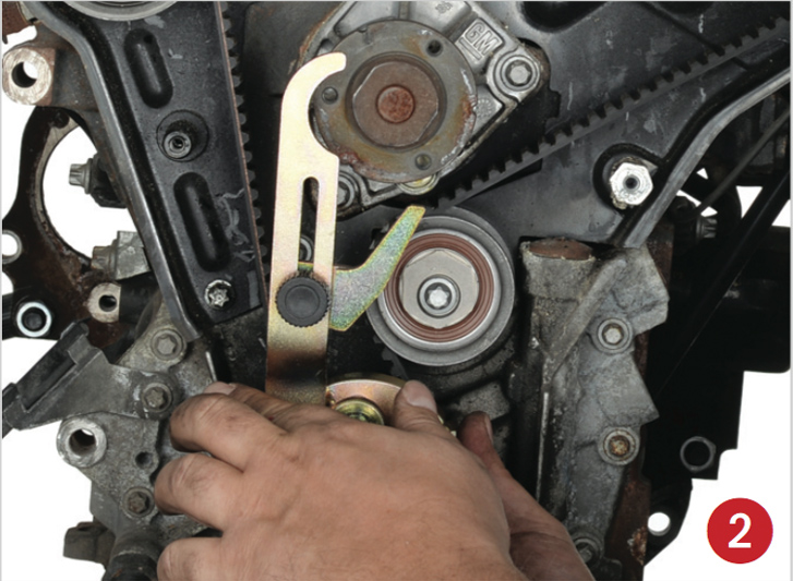
Attach lock ring tool for crankshaft OE (KM-800-10) to the crankshaft gear (Fig 2) and slowly turn the crankshaft in the direction of engine rotation until the lever of the lock ring tool is against the water pump (Fig 3). The notches on the camshaft gears must now align with the grooves in the rear timing belt guard, and the notches on the crankshaft must align with the grooves in the lower housing at the 6 o’clock position (Fig 4).
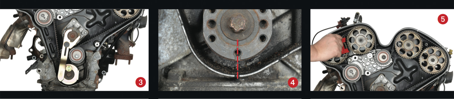
Place the retaining tool for camshaft OE (KM-800-1) red with the designation “Top” on top between camshaft gears “1” and “2” (Fig 5 and 6). If the retaining tool cannot be inserted, then remove the top timing belt bend pulley (Fig 7) and turn it on the cam with chuck key MKM-6038 or water pump pliers until the tool can be inserted.
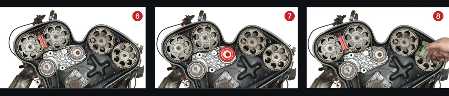
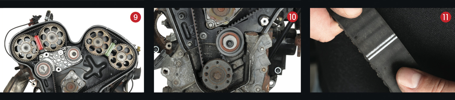
Place the retaining tool for camshaft OE (KM-800-2) green with the designation “Top” on top between camshaft gears “3” and “4” (Fig 8 and 9). If the retaining tool cannot be inserted, then remove the bottom timing belt bend pulley (Fig 10) and turn it on the cam with chuck key MKM-6038 or water pump pliers until the tool can be inserted. The engine is now fixed at TDC position.
Loosen the nut on the tensioner pulley and loosen the timing belt on the cam by turning the 5mm hexagonal socket clockwise. The timing belt can now be removed.
Installation:
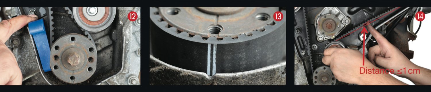
Install the new components of the timing belt kit. Check the remaining components such as the camshaft gear and crankshaft gear for damage. Fit the timing belt (the timing belt is marked with guide marks and the direction of travel). First, place the marking with the double bar (Fig 11) on the crankshaft gear and use chock OE (KM-800-30) to securely clamp it on the left side so that the timing belt is fixed and cannot skip (Fig 12).
The grooves in the crankshaft gear must be aligned with the double bar (Fig 13). Place the timing belt in a clockwise direction over the tensioner pulley, camshaft gears “1” and “2”, top timing belt bend pulley, camshaft gears “3” and “4”, and the lower timing belt bend pulley. In doing so, you must ensure that the timing belt is not buckled or folded while fitting. The timing belt must be taut on the pull side between gear wheels “3” and “4” and the lower bend pulley. The deflections in the timing belt may not be more than 1cm (Fig 14).
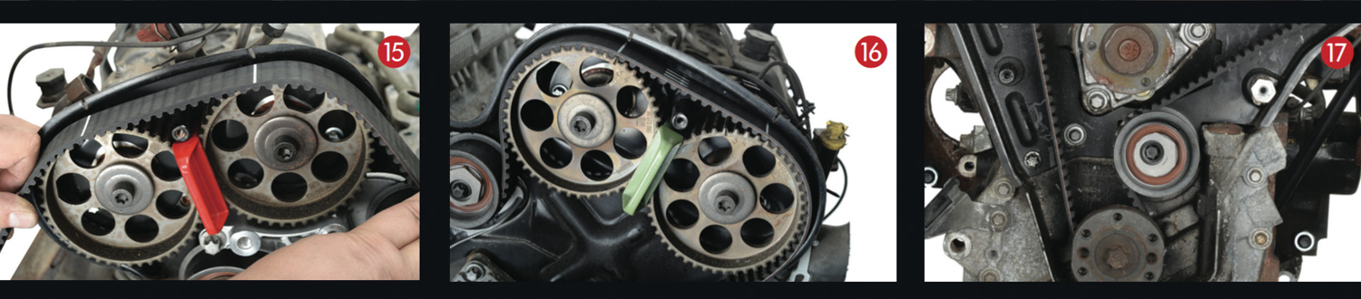
The marking aids on the timing belt must correspond to the TDC markings on the camshaft gears and the rear timing belt guard (Fig 15 and 16).
Turn the cam of the lower tensioner pulley with chuck key MKM-6038 or water pump pliers in a counterclockwise direction until the top of the cam is at the 2 o’clock position (Fig 17).
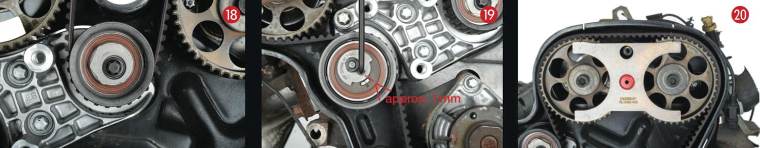
Turn the cam of the top tensioner pulley with chuck key MKM-6038 or water pump pliers in a counterclockwise direction until the top of the cam is at the 11 o’clock position (Fig 18).
Loosen the nut on the timing belt tensioner pulley and turn it in a counterclockwise direction with the 5mm hexagonal socket until the marking of the cam is approx. 1mm above the top edge of the adjustment mark (Fig 19). Tighten the nut on the tensioner pulley.
Remove the lock ring tool for the crankshaft, and the chuck and retaining tools for the camshaft. Turn the crankshaft two revolutions in the direction of engine rotation and place the engine back at TDC position, then place the lock ring tool for the crankshaft OE (KM-800-10).
The guide marks on the timing belt will no longer match up with the markings on the camshaft gears after one or more revolutions. The guide marks are only for assembly.
The tension of the timing belt must now be readjusted. Attach inspection gauge OE (KM-800-20) to camshaft gears “3” and “4”. The markings are before the markings on the inspection gauge OE (KM-800-20) (i.e. before the TDC point).
Turn the cam of the lower bend pulley in a counterclockwise direction using chuck key OE (MKM-6038) or water pump pliers until the top of the cam is at approx. 12 o’clock position and the markings on the camshaft gears and the inspection gauge OE (KM-800- 20) align (Fig 20).
Tighten the lower bend pulley with 40 Nm. Camshaft gears “3” and “4” must be adjusted exactly before camshaft gears “1” and “2” are adjusted.
Remove the inspection gauge and place on the camshaft gears “1” and “2”. The markings are before the markings on the inspection gauge OE (KM-800-20) (i.e. before the TDC point).
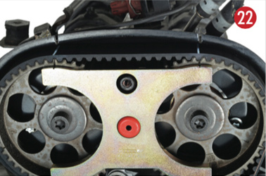
Turn the cam of the top bend pulley in a counterclockwise direction using chuck key OE (MKM-6038) or water pump pliers (Fig21) until the top of the cam is at approx. 9 o’clock position and the markings on the camshaft gears and the inspection gauge OE (KM-800-20) align (Fig 22). Tighten the top bend pulley with a force of 40Nm.
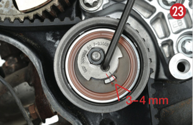
Loosen the nut on the timing belt tensioner pulley and turn it in a counterclockwise direction with the 5mm hexagonal socket until the marking of the cam is approx. 3-4mm above the middle marking of the adjustment mark (Fig 23). Tighten the nut of the tension pulley with a force of 20Nm.
Remove the retaining and lock ring tools, then turn the crankshaft two revolutions in the direction of engine rotation and place the engine back at TDC position; then place the lock ring tool for the crankshaft OE (KM- 800-10). Check settings of all camshafts.
Attach inspection gauge OE (KM-800-20) to camshaft gears “3” and “4”. Markings on the camshaft gears and the inspection gauge OE (KM-800-20) align (Fig 20). If the markings do not align, adjust again as under point nine.
Attach inspection gauge OE (KM-800-20) to camshaft gears “1” and “2.” Markings on the camshaft gears and the inspection gauge OE (KM-800-20) align (Fig 22). If the markings do not align, adjust again as under point 11. Remove the retaining and lock ring tools, then assemble and complete in the reverse of the order used in disassembly.
Record the replacement of the original ContiTech timing belt on the sticker provided and affix it in the engine compartment (Fig 23).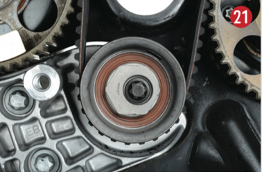
Test-run the engine or take a test drive.