A clutch fitment guide for a 2008 Audi A3 1.9 TDI; Clutch and DMF replacement tips.
Audi launched the A3 in 1996, with the second generation released in 2003 and the new model A3 following in 2012. Sharing the same platform as the Audi TT, VW Golf, Caddy and Touran, Seat Leon, Toledo and Skoda Octavia, the A3 has three model styles (three door, five door and Cabriolet) and is available in two wheel drive or four wheel drive (Quattro) variants.
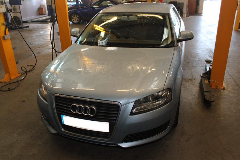
This month’s clinic features a 2008 Audi A3 1.9 TDI (three door, two wheel drive) which had covered over 129,000 miles and was booked in because the owner had noticed ‘judder’ when driving. Because this symptom was more noticeable when using the clutch, the suspicion before diagnosis was that there may be a fault with the flywheel.
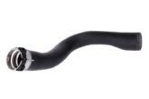
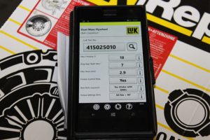
Recommended fitting time: 3.7 Hours Parts fitted: 415025010 (DMF); 411013310 (Flywheel bolts); 623309400 (Clutch kit)
Special Equipment
The special workshop equipment we used for this repair was a two-post ramp, engine support beam, transmission jack, Dual Mass Flywheel (DMF) test kit and a Self-Adjusting Clutch (SAC) installation kit.
With the vehicle placed on the ramp, locate the locking wheel bolt key and slacken the N/S/F wheel. Then slacken the N/S/F hub bolt, raise the bonnet, disconnect and remove the battery, battery housing and battery tray. The next step is to disconnect the air mass meter and remove the air filter assembly and hose to the inlet manifold – this will give you good access to the top of the gearbox.
Remove the gear linkage assembly by releasing the two “C” clips and removing the three bolts. Disconnect the multi-plug for the reverse light switch, then remove the two bolts that retain the slave cylinder. The hydraulic pipe can then be unclipped and swivelled up to give better access to the bolts. Remove the slave cylinder from the bell housing and stow the gear linkage and slave cylinder against the bulkhead and secure, if required.

At this point the top bell housing bolts can be removed with the engine earth connected to the one. Disconnect the starter motor wiring and then the top starter motor bolt. Now fit an engine beam to support the engine and gearbox and, once fitted, the top gearbox mounting can be removed. Now raise the vehicle, remove the N/S/F wheel, remove the N/S driveshaft flange bolts and the hub bolt. The N/S driveshaft can now be removed at the gearbox end and then removed from the hub. Remove the bolts from the O/S driveshaft inner joint flange and disconnect from the gearbox. We can now remove the O/S drive flange from the gearbox by removing the Allen bolt from the centre of the flange to aid gearbox removal.
Remove the lower gearbox mounting/stabiliser unit from the gearbox and front sub-frame, then remove the bottom starter motor bolt and the starter motor. Lower the engine/gearbox on the engine beam to gain some clearance for gearbox removal and, supporting the gearbox with a transmission jack, remove the remaining bell housing bolts and then the gearbox with the transmission jack.
Service life
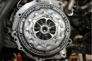
With the gearbox removed the cause of the judder was now visible – the DMF hadn’t returned to its rest position, indicating that it had reached the end of its service life.

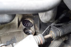
As a result, the DMF tester kit was now not required. Removing the clutch assembly showed signs of normal wear that would be expected at this vehicle’s mileage. We held the primary mass of the flywheel by the starter ring gear and rotated the secondary mass back to the neutral position with a two pin wrench. The bolts were now visible for removal. After removing the flywheel we carried out a visual inspection of the rear main oil seal and this showed no signs of leakage. We then mounted the new flywheel. Using Schaeffler’s DMF Checkpoint App, the tightening torque settings could easily be obtained and the flywheel torqued.
Before fitting the clutch, confirm the clutch plate fits the splines of the gearbox input shaft. Mount the new Self-Adjusting Clutch using Schaeffler’s special tool (400 0237 10), combining the clutch alignment tool to eliminate any rotation of the adjuster ring and to ensure the clutch pressure plate is installed evenly, thus removing the risk of any clutch judder.
With the clutch installed, ensure the three yellow adjuster ring springs are still compressed, confirming the adjuster ring has not de-adjusted.
Clean the bell housing of the gearbox, replace the release bearing and ensure that there is no wear to the clutch release fork and gearbox snout. Then lubricate the pivot points that are metal-to-metal with a smear of high melting point grease. Ensure the dowels are located properly on the engine and that the sandwich plate is positioned correctly.
Refit the gearbox and secure with the bell housing bolts. At this point you can check if there is a small amount of ‘freeplay’ on the clutch fork by pressing it with your finger to confirm correct installation. Refit all components in the reverse order and torque the bolts to the manufacturer’s specifications, remembering to reset electrical items because the battery has been disconnected.
When starting the car, the ABS, ESP and electric steering warning lights may be illuminated so you should turn the steering from lock-to-lock to reset the steering system. Finally, a short test drive will reset the ABS and ESP systems so no warning lights are illuminated.