I was asked to look at a Mitsubishi Shogun that had come to us with the EML on. This had already been looked at by another garage, the customer had taken it back to them twice with the same problem and they had failed to fix it, despite money already spent.
As we all know these jobs can be a problem – the customer’s budget had already been spent on unnecessary parts and time by the previous garage, and the pressure was on to get the diagnosis right first time. I love a challenge though so agreed to take the job on. After interrogating the customer I started the process – the first thing was the code read.

This displayed fault code: P0125 – Insufficient coolant temperature for closed loop fuel control – a code I have never seen before.
After completing a visual check I could see that a thermostat and an engine coolant temperature sensor had been fitted by the previous garage. I decided to monitor live data from cold to running temperature but couldn’t be 100% sure what the issue was and was just checking that nothing else out of the ordinary was being picked up.
Live data showed engine coolant and air temp as normal, but scrolling down the data I noticed bank 2, sensor 1 only reached a maximum of 0.24v during the whole warm up period, which was about 30 minutes. This was the only thing that stood out to me. It obviously wasn’t right so I now needed to find out what was happening and whether this could be related to my fault code.
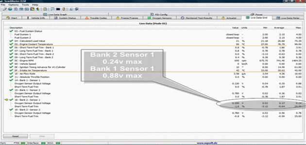 Live Shogun data
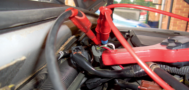
Connecting the scope
The connection block for both O2 sensors was fairly accessible at the bulkhead and resistance across the heater circuit was 7 Ohms. Once the engine had cooled down again I connected the scope and used all four channels. I measured signal, supply, duty cycle for heater and heater current and earthed the scope at the sensor.
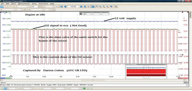 O2 sensor test
Everything apart from the signal was normal, as serial data showed bank 2, sensor 1 was around 0.2v. I wanted to see what the sensor would do with a snapped throttle, so I freed up the channels and introduced bank 1, sensor 1 with bank 2, sensor 1 and throttle position.
By snapping the throttle we would expect to see a rich state throughout the WOT (Wide Open Throttle). As highlighted on the diagram (below) the green trace is bank 2, sensor 1 on WOT.
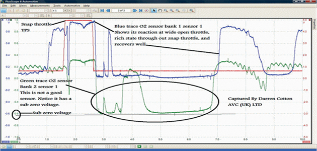 O2 sensor at sub zero
Notice how the sensor goes sub-zero – something that I have only seen a few times. This problem would have never been discovered if it hadn’t been for the Picoscope and I would be amazed if most other garages didn’t struggle without one. Don’t get me wrong here, this was a complete learning curve for me as I have never experienced the fault code before, and didn’t really have a diagnostic structure in place. It was a kind of ‘earn as you learn’ repair, either way, a new O2 sensor was needed.
The reason
The O2 sensor will produce voltage based on the difference across the two plates of the sensing element. The inner plate will contain a chamber of fresh air (reference chamber) and the outer element senses the oxygen content of the exhaust. What we possibly have here is that the sensing element containing our fresh air could be cracked and as the vehicle is revved the pressure of the exhaust gases increase and some of the gases will escape into the reference chamber.
This gives less oxygen and creates a potential difference across the two plates of the sensing element – but in the opposite direction – hence why we see a sub-zero voltage.
No fault codes present
With a new sensor fitted and the fault code cleared an extended road test was performed. The scan tool was reconnected to find that there were no fault codes present or pending. The Picoscope was infallible in this case, so it just shows that investing a bit of time in your work and purchasing the right tools will mean that you can narrow down the chances of unnecessary parts being fitted.