Fault diagnosis can be a considerably time consuming part of a vehicle technician’s working day. Some faults are straightforward and easy to rectify, but this is not always the case. Whilst tracing a fault, when a diagnostic warning light becomes illuminated, the first step is to read the stored fault codes. This is the gateway to finding the cause of the issue. Fault diagnosis can be confusing, but breaking it down in stages will simplify the task. Sealey explains more.
We have retrieved a fault code – but what does this actually tell us? Simply put, it tells us that the data being examined by the control unit on the car is different to the data expected. The car then records that there is a defect. At this point we need to analyse what this fault code represents and what could have generated it. To do this we need to ascertain what data is being analysed.
 Take the function of a manifold pressure sensor (MAP sensor), for example. This device responds to changes in the intake manifold (vacuum). The PCM (power control module) supplies a 5V feed to the sensor and a resistor in the sensor varies the return voltage to the PCM, depending upon engine load to indicate the vacuum in the manifold. The return voltage should be between 1 and 5V – a return voltage of less than 1V would give a fault code of P0107. If the return voltage is too low, it’s questionable whether or not to replace the sensor. However, we first need to discover if this component is the cause of the low return voltage.
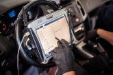
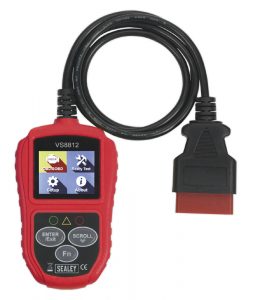
The Sealey VS8812 is an entry level fault code reader and among its many functions is the capability to read the MAP sensor voltage. If the return voltage with the engine running is under 1V, turn the engine off and unplug the sensor.
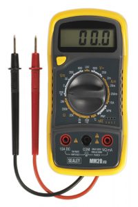
Next, using a voltmeter – such as the Sealey MM20 Multimeter, which is ideal for this task – check for a 5V feed to the sensor.
There is now a series of possibilities to consider:
 1. There is no 5V feed to the sensor. This could indicate a broken wire between the sensor and the PCM, or a faulty PCM. Again, the MM20 Multimeter can check the PCM output voltage and after disconnecting the wire from the PCM, the MM20 Multimeter can be used to check the wiring continuity.
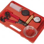
2. If there is a 5V feed to the sensor, it is an easy component to test. The Sealey VS402 Vacuum Test & Brake Bleeding Kit can be used to provide a vacuum to the sensor. By applying a vacuum and
using the MM20 Multimeter, you can check for a voltage variation from the sensor output side as the vacuum changes. If the voltage changes, the sensor is working. The wiring back to the PCM can now be checked using the MM20 Multimeter.
3. If the voltage does not change, a new MAP sensor is required. By using these three inexpensive tools, you can perform a correct diagnosis just by finding out how a component works and carrying out some very simple tests.