

This regular series of technical articles from Bosch focuses on how to get the best out of its ESI[tronic] 2.0 software, which is used in conjunction with the KTS range of diagnostic tools for vehicle fault diagnosis and service function procedures.
In this issue we’re going to look through the diagnostic capabilities and usefulness of the Global OBD II functions offered by the ESI 2.0 software, which can often be overlooked in vehicle diagnosis. The American OBD (On Board Diagnosis) standard was introduced in 1988 in California in an attempt to reduce traffic-related air pollution. OBD regulations involve self monitoring by electronic control units of all vehicle systems and components which influence exhaust emissions. In 1996 this standard was succeeded by OBD II to meet with more stringent emission limit values. In Europe, EOBD (European On Board Diagnostics) is based on the more comprehensive OBD II concept and applies to gasoline vehicles registered from 01/01/2001 and diesel vehicles registered from 01/01/2004.
System fault
The standardised OBD system enables constant monitoring of vehicle components influencing exhaust emissions. If a system fault is detected that leads to an increase in emissions, the driver is informed accordingly with a malfunction indicator lamp (MIL). If the fault that is detected is severe enough to
cause damage to a component such as the catalytic converter then the MIL will flash and action can be taken, such as fuel injector shut off by the control unit to protect components at risk. Fault codes will be stored by the controller with a description of the malfunction and relevant information.
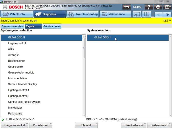
The five digit OBD fault codes always begin with ‘P0’ and have standardised description designations for all VMs. For example ‘P0301’ will mean ‘Cylinder 1 misfire detected’,regardless of the vehicle make and model. For system analysis and fault finding, the OBD system data is accessed via the 16 pin diagnosis connection to the Bosch KTS using one of the five permitted communication protocols. The Bosch ESI 2.0 software offers the Global OBD II (EOBD) diagnosis mode at the top of the ‘System group selection’ list for every applicable vehicle selection (RB key) (see below).
Typically the Global OBD II functions consist of diagnosis modes one to nine and in Bosch ESI 2.0 there are also some useful extra features (see below).
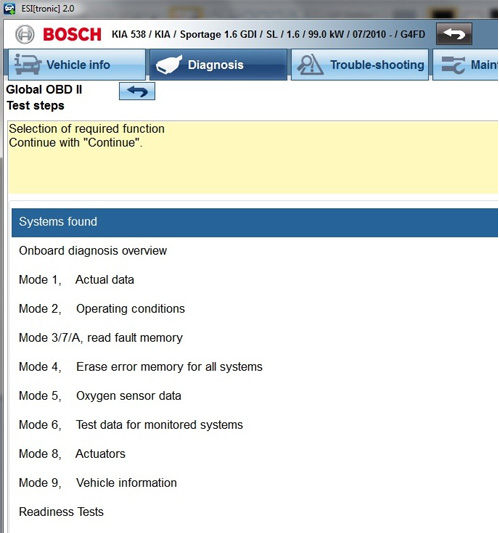
The first extra feature in ESI 2.0 on the selection screen is ‘Systems found’. This will display compatible ECUs and usually lists the engine control and transmission control, if the vehicle has an automatic gearbox.
The next additional feature is the ‘Onboard diagnosis overview’, which is a quick and accurate method to assess the state of the vehicle system and can provide essential data to help you find an emissions related fault. Now let’s go through the nine OBD modes mentioned earlier:
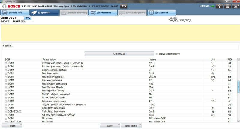
Mode 1: reads the actual data that is processed by the ECU from the sensor input signals. The available data depends on the vehicle configuration and, in true KTS style, can be displayed in different ways to suit your preference. From the start, you’re presented with a full scrollable list of values displayed as live readings. The standard OBD II PIDs (Parameter identifications), as defined by the Society of Automotive Engineers standard – SAE J1979, are shown in the right hand column.
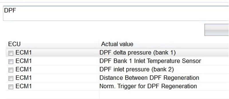
You may be surprised by the large amount of data available on some cars, such as DPF, NOx and SCR information on the very latest diesel cars (see below).
You can manipulate and filter the ‘Actual data’ list with several methods. Firstly, our good friend the ‘search bar’ is present at the top of the data field. Typing any text into here will instantly change the list to only display actual values that contain that text in their name (see below).
Scrolling list
All values are displayed on a scrolling list and, if you want to be more specific, you can select up to any eight particular values by clicking the ‘check box’ in the left ECU column and then choosing the ‘Show selected only’ option to filter out values you don’t want displayed. As we covered in a previous article, the
selected OBD actual values can also be displayed in a colourful graph format by using the ‘Time profile’ F6 soft key (see below).
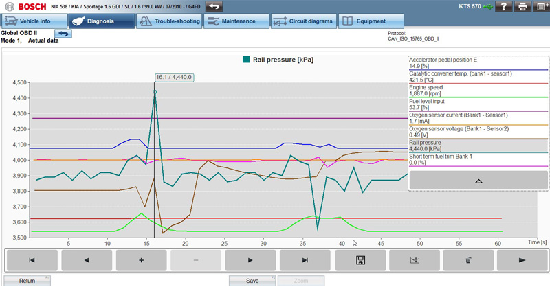
Some really useful values are usually present in the OBD actual data program, such as ‘Distance travelled while MIL is activated’ and ‘number of warm up cycles since DTC clear’. This type of information can be
essential if you have a problem vehicle with a suspicious repair history.
Mode 2: provides freeze frame data associated to any stored DTCs which, if supported by the controller, can give a helpful guide as to what the ambient conditions were when that particular fault was logged. This ‘snap shot’ information is especially beneficial when testing for intermittent faults.
Mode 3, 7 & A: are grouped together to report any stored fault codes, whether they are confirmed, pending or permanent, along with associated readiness tests status (see below).
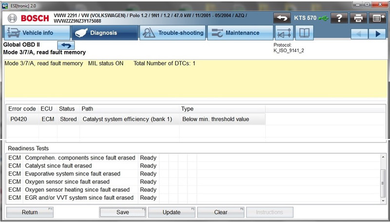
The fault code, status, description and type are all listed. As the OBD II fault codes are standardised the information will be reliable and there won’t be any unknown descriptions. The error memory can be saved, cleared or re-read directly using the soft keys along the bottom of the screen.
Mode 4: is used to erase the fault code error memory for the OBD systems after repairs have been carried out. When the fault code memory is cleared within the OBD system, the adaptation values and readiness tests are also reset. A specific road test (drive cycle) will need to be performed in order for
the OBD internal checks to be completed. Usually a fault code of ‘P1000’ will be logged until the internal systems OBD checks are satisfied.
Mode 5: provides more in-depth ‘Oxygen sensor data’ and air/fuel mixture test results, but is not supported by all vehicle brands.
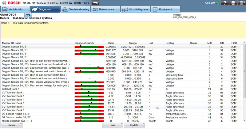
Mode 6: is the ‘Test data for monitored systems’ and gives useful information, such as Lambda sensor parameters. Graphical display bars of the values contain red and green colour coding which give a quick guide as to whether the parameters are running within their tolerances (green) or outside them (red).
Oxygen sensor and variable valve timing data, along with misfire counters, can be a real emissions fault finding aid (see below).
Mode 8: is the ‘Actuators’ function and can offer on board system activations like an evaporative system leakage test, but these tests may not be supported by all European vehicles.
Mode 9: holds ‘Vehicle information’ including the chassis number (VIN) and engine/automatic transmission control unit calibration numbers and test condition counters.
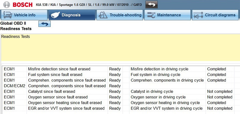
Readiness tests: are the last selection on the selection list and report the status of the monitor tests of either ‘ready’ or ‘not ready’ and whether the test is ‘completed’ or ‘not completed’ (see below).This operation acts as a valuable confirmation of a successful repair to the system if all OBD monitor tests are completed and passed.
Soft key
As with previous topics we’ve covered in these articles, whenever the ‘Save’ soft key is shown along the bottom of the ESI 2.0 screen, any data that is displayed on screen will be added to the job ‘protocol’ report that can be saved and printed for reference. In most cases the Global OBD II function in Bosch ESI 2.0 gives you an additional way to interrogate the vehicle power train systems for emissions related data.
The method described here will sometimes give more specific detail about the engine fuel trim analysis, closed loop control and associated components that are critical to keep the vehicle exhaust emissions within their prescribed limits.
The Global OBD II functions of ESI 2.0 can be a great diagnostic aid when used to supplement the specific engine control diagnosis. We’ve seen some cars that will store error codes in the OBD II memory
which may not be evident in the manufacturer-specific ECU software. With this in mind, it’s always worth checking the OBD II diagnostic functions within Bosch ESI 2.0 when you’re working on a vehicle
with emissions related faults, to ensure that no vital data has been missed.
The OBD II capabilities within Bosch ESI 2.0 and on board system test monitors provide a more robust diagnostic process which can give you more confidence in returning a fully tested and verified vehicle
back to the customer after a repair.