A full belt replacement guide on a 2L Vauxhall Insignia CDTI A20DTH from Schaeffler REPXPERT.
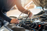
In what has been a busy month for REPXPERT’s Alistair Mason, he also replaced the timing belt, water pump and auxiliary belt on a 2015 Vauxhall Insignia, which was fitted with a 2.0 CDTI A20DTH engine – one that is also shared between Saab and Fiat. The timing belt and auxiliary drive belt, both of which have a recommended service time of 100,000 miles or 72 months, have a repair time of almost two and three-quarter hours.
On this occasion, the engine was identified as an ‘interference’ type engine. Therefore, in the event of timing belt failure, the likelihood of engine damage is extremely high.
It is important that belt tensioning is performed on an engine at ambient room temperature. Always turn the engine in the normal direction of rotation, unless advised otherwise by the OEM fitting instructions, while recommended manufacturers’ torque values should always be used. It is also recommended that tensioners and idlers be changed when replacing the timing belt.
For this repair, a two-post ramp, engine support and Vauxhall engine timing tool set are required. In addition, before any work is carried out on the vehicle, the battery earth cable needs to be disconnected.
Step-by-step procedure
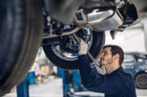
With the vehicle placed on the ramp, open the bonnet and remove the plastic engine cover. With the vehicle still on the ground, slacken the O/S/F wheel and raise the ramp to gain access to the underside. Remove the engine/gearbox under-shield retaining screws and lower the shield. It is worth noting that the shield is fixed at the front. Next, lower the ramp to waist height and remove both the O/S/F wheel and wheel arch liner that is retained by Torx screws and plastic clips.
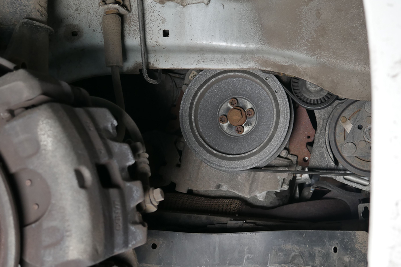
With the wheel arch liner removed, slacken the four crankshaft pulley bolts (see below) and then disconnect the auxiliary belt by releasing the tension.
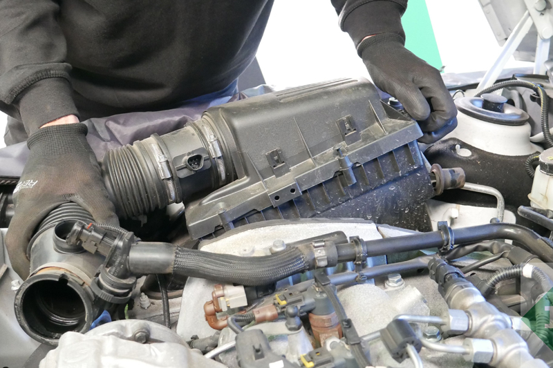
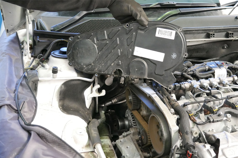
At this point, detach the four crankshaft pulley bolts. For this scheduled repair, the required engine support attaches to the front sub-frame and supports the engine from the underside – this needs to be attached before lowering the ramp. With the ramp lowered, disconnect the air mass meter and breather pipe, before removing the air filter assembly (see below) and the upper timing belt cover (see below).
The engine mounting and bracket assembly can also be taken away, once the engine is supported.
Timing belt removal
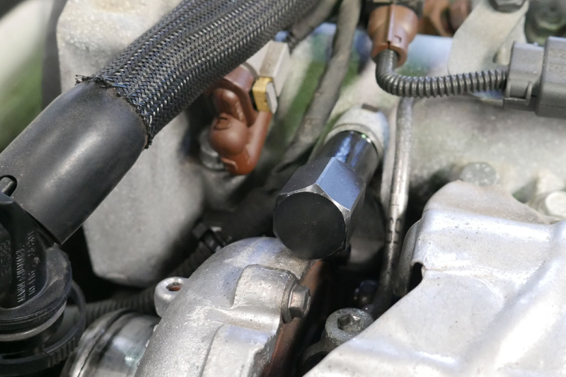
At this point, the timing belt is now fully accessible and can be removed. This is achieved by firstly rotating the engine in a clockwise direction until the notch on the camshaft pulley is at the 12 o’clock position. Next, dislodge the blanking cap on the cam cover using an Allen key, insert the camshaft locking pin into the hole, hold the locking pin against the camshaft and slowly rotate the engine until the locking pin fits into the camshaft.
Screw the locking pin into the cam cover until fully home (see below), raise the ramp to waist height, remove the bolt from the oil pump housing and insert the crank locking tool alignment stud (see below).
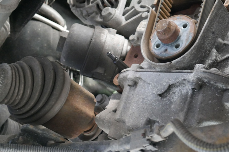
It is then possible to install the crankshaft locking tool onto the crank and bolt into place (see below).
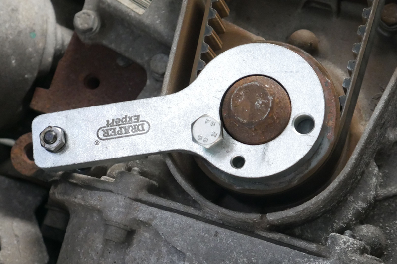
With the crank and camshafts correctly aligned and locked into place, loosen the camshaft pulley retaining bolt using a counter-hold tool to support the pulley. Once slackened, relax the timing belt tensioner bolt so it can rotate but not tip, and then remove the crankshaft locking tool and then the timing belt.
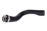
As the water pump is driven by the timing belt, the pump must also be replaced. Drain the coolant by removing the bottom hose from the radiator. Once drained, refit the bottom hose and then remove the water pump retained by three Allen bolts.
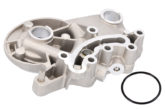
Next, clean the gasket mating area on the cylinder block, as well as any coolant that may have got into the timing belt area. Now fit the new water pump, ensuring the gasket has been located properly, and torque to the manufacturer’s specification.
As standard practice, replace the old timing belt tensioner, idlers and bolts with new ones supplied in the kit, and torque the idlers to the manufacturer’s specification.
Fitting the timing belt to the crankshaft pulley
The timing belt can now be fitted to the crankshaft pulley. To do this, the white line on the timing belt needs to be aligned with the notch on the crankshaft pulley at the 9 o’clock position. With the belt in position, fit the crankshaft locking tool and secure it. Fit the timing belt in a clockwise direction, ensuring the white marks on the timing belt align with the marks on the high-pressure fuel pump and camshaft (see below).
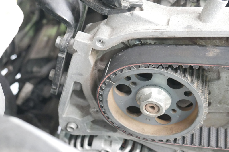
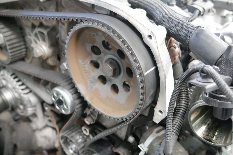
Finally, ease the belt onto the idler before the crankshaft pulley. Once the timing belt has been installed and all the white lines align, set the belt tension by sliding the tensioner towards the high-pressure fuel pump – a suitable tool may be required for this.
For this type of repair, an 8mm bolt needs to be screwed in, located directly underneath the timing belt tensioner, which can be used as a leverage point. Position a small lever against the tensioner base plate, and ease the tensioner towards the high-pressure fuel pump until its pointer aligns with the hole/reference point on the base plate.
Once in the correct position, tighten the tensioner and torque to the manufacturer’s specification. Now tighten and torque the camshaft pulley by using a counter-hold tool to support the camshaft. Remove the camshaft and the crankshaft locking tools, before rotating the engine two complete revolutions. Next, refit the camshaft and crankshaft locking tools to ensure the engine timing is correct, as well as checking the tensioner pointer is still in the correct position – if all is confirmed, refit all parts in reverse order of removal.
Replacing the auxiliary drive belt system
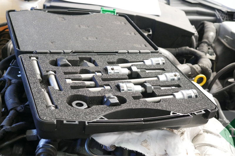
For this type of repair, with the auxiliary drive belt system hitting its service interval, the overrunning alternator pulley was replaced (Fig 9) using Schaeffler’s INA alternator pulley tool kit (see below).
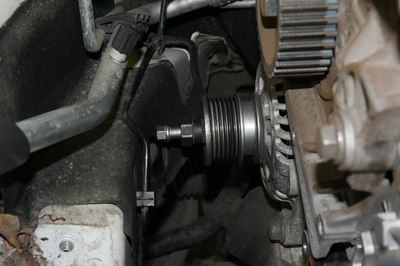
The tensioner and idlers were also switched. With the repair complete, fill the cooling system with the correct specification of coolant, and run the engine. Now carry out a full road test, ensuring the cooling system has fully bled, and then allow the engine to cool, and check the coolant level.